Introduction
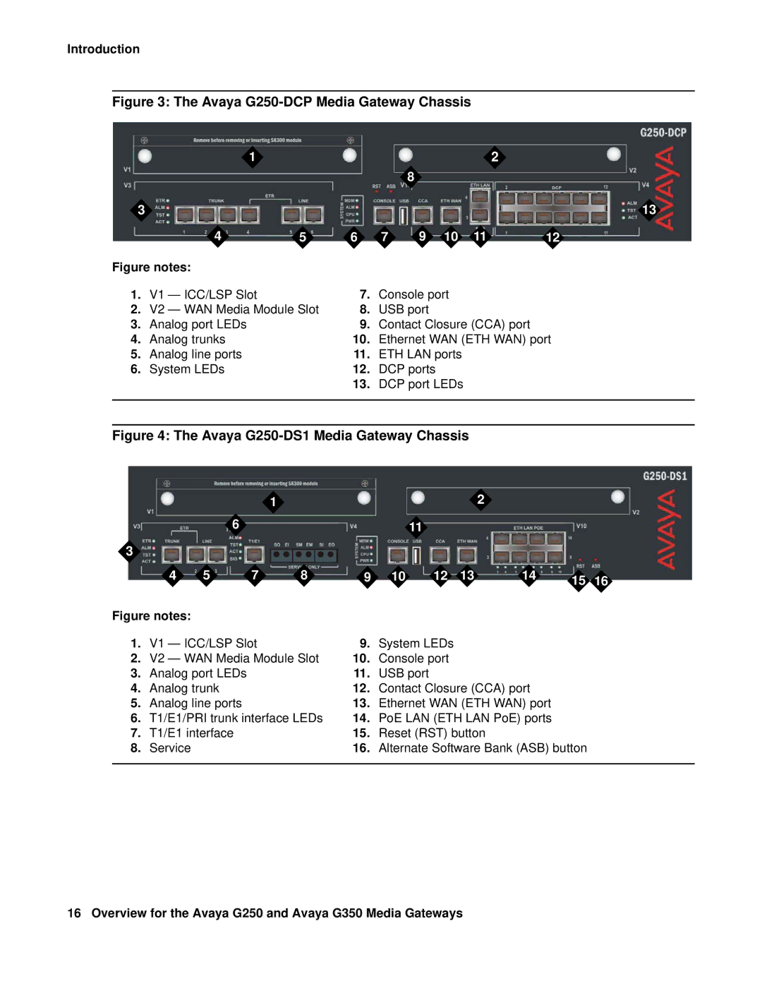
Figure 3: The Avaya G250-DCP Media Gateway Chassis
| 1 |
|
|
|
|
| 2 |
|
|
|
|
|
| 8 |
|
|
|
3 |
|
|
|
|
|
|
| 13 |
| 4 | 5 | 6 | 7 | 9 | 10 | 11 | 12 |
Figure notes: |
|
|
|
|
|
|
| |
1. | V1 — ICC/LSP Slot |
| 7. | Console port |
|
| ||
2. | V2 — WAN Media Module Slot | 8. | USB port |
|
|
| ||
3. | Analog port LEDs |
| 9. | Contact Closure (CCA) port |
| |||
4. | Analog trunks |
| 10. | Ethernet WAN (ETH WAN) port | ||||
5. | Analog line ports |
| 11. | ETH LAN ports |
|
| ||
6. | System LEDs |
| 12. | DCP ports |
|
|
| |
13.DCP port LEDs
Figure 4: The Avaya G250-DS1 Media Gateway Chassis
|
|
|
| 1 |
|
|
| 2 |
|
|
|
|
| 6 |
|
|
| 11 |
|
|
|
|
|
3 |
|
|
|
|
|
|
|
|
|
|
|
| 4 | 5 | 7 | 8 | 9 | 10 | 12 | 13 | 14 | 15 | 16 |
Figure notes: |
|
|
|
|
|
|
|
|
|
| |
1. | V1 — ICC/LSP Slot |
| 9. | System LEDs |
|
|
|
| |||
2. | V2 — WAN Media Module Slot | 10. | Console port |
|
|
|
| ||||
3. | Analog port LEDs |
|
| 11. | USB port |
|
|
|
|
| |
4. | Analog trunk |
|
| 12. | Contact Closure (CCA) port |
|
| ||||
5. | Analog line ports |
|
| 13. | Ethernet WAN (ETH WAN) port |
|
| ||||
6. | T1/E1/PRI trunk interface LEDs | 14. | PoE LAN (ETH LAN PoE) ports |
|
| ||||||
7. | T1/E1 interface |
|
| 15. | Reset (RST) button |
|
|
| |||
8. | Service |
|
|
| 16. | Alternate Software Bank (ASB) button |
| ||||
|
|
|
|
|
|
|
|
|
|
|
|