LH 4, LH4r, LH 3, NetServewr specifications
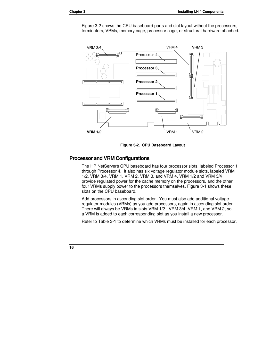
The HP NetServer series, particularly the LH models (LH 3, LH 4, and LH 4r), represents a significant advancement in server technology during the late 1990s and early 2000s. These servers were designed for small to medium-sized businesses, providing reliable performance, robust features, and a cost-effective solution for various computing needs.The HP NetServer LH 3, introduced in 1996, was a dual-processor machine that tapped into the capabilities of the Intel Pentium Pro. It was notable for its scalability, supporting up to 4GB of RAM, which was impressive for its time. Its architecture enabled it to handle multiple workloads simultaneously, making it ideal for web hosting and database applications. The server was equipped with advanced storage options, featuring SCSI interfaces and a range of RAID configurations to ensure data redundancy and speed.
Moving to the LH 4, released in 1997, this model pushed the boundaries further with enhancements in processing power and efficiency. The LH 4 supported Intel’s newer architectures, including the Pentium II processors, boosting performance for demanding applications. Its design emphasized hot-swappable components, allowing for easier maintenance without downtime — a crucial feature for business continuity. The LH 4 supported larger memory configurations, up to 8GB, facilitating more significant data processing tasks and multitasking capabilities.
The HP NetServer LH 4r, a rack-mounted version of the LH 4, provided a compact form factor suitable for environments where space was at a premium. This model was particularly popular among enterprises that required high-density computing solutions. The LH 4r maintained the reliability and performance characteristics of its predecessor while providing additional features such as advanced thermal management and improved network options, including gigabit Ethernet.
Key technologies across these models included HP’s Dynamic Smart Array technology, which optimized data storage and retrieval. The inclusion of Windows NT as a supported operating system ensured compatibility with contemporary applications, enabling businesses to leverage existing software investments.
In summary, the HP NetServer LH series, especially the LH 3, LH 4, and LH 4r models, represented a remarkable evolution in server capabilities. With their robust performance, flexibility, and user-centric features, these servers addressed the burgeoning demands of the business IT landscape, helping organizations achieve their operational goals. Their legacy lives on in the server technologies that continue to evolve today.

