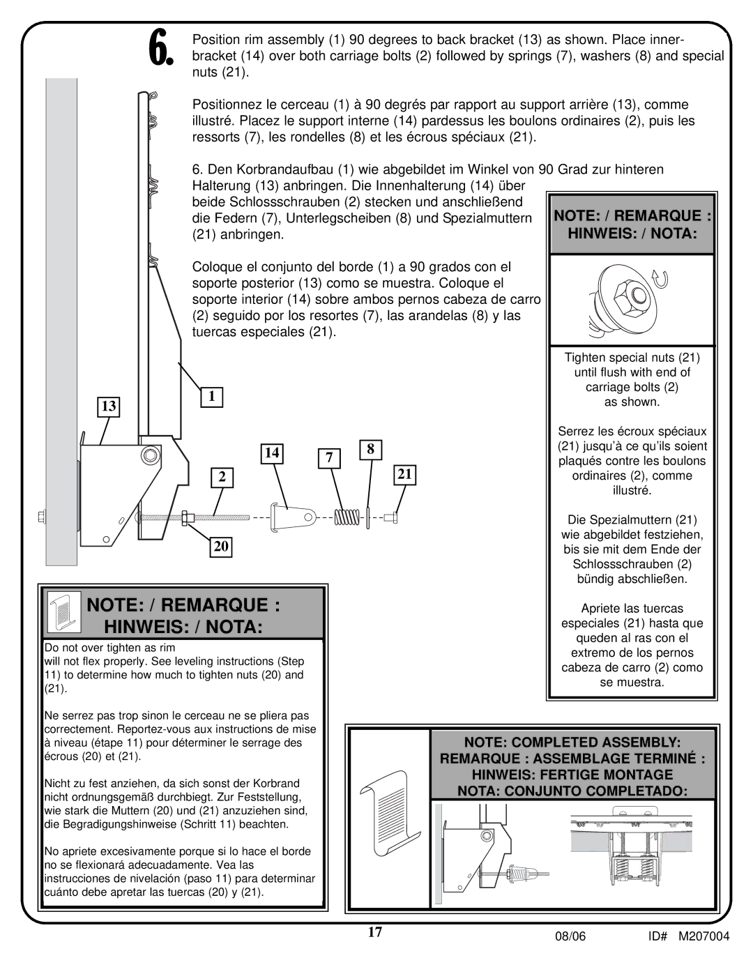
6. Position rim assembly (1) 90 degrees to back bracket (13) as shown. Place inner- bracket (14) over both carriage bolts (2) followed by springs (7), washers (8) and special nuts (21).
Positionnez le cerceau (1) à 90 degrés par rapport au support arrière (13), comme illustré. Placez le support interne (14) pardessus les boulons ordinaires (2), puis les ressorts (7), les rondelles (8) et les écrous spéciaux (21).
6. Den Korbrandaufbau (1) wie abgebildet im Winkel von 90 Grad zur hinteren Halterung (13) anbringen. Die Innenhalterung (14) über
beide Schlossschrauben (2) stecken und anschließend die Federn (7), Unterlegscheiben (8) und Spezialmuttern (21) anbringen.
Coloque el conjunto del borde (1) a 90 grados con el soporte posterior (13) como se muestra. Coloque el soporte interior (14) sobre ambos pernos cabeza de carro
(2) seguido por los resortes (7), las arandelas (8) y las tuercas especiales (21).
13
1
14
2
20
7
8
21
NOTE: / REMARQUE :
HINWEIS: / NOTA:
Do not over tighten as rim
will not flex properly. See leveling instructions (Step
11)to determine how much to tighten nuts (20) and
(21).
Ne serrez pas trop sinon le cerceau ne se pliera pas correctement.
àniveau (étape 11) pour déterminer le serrage des écrous (20) et (21).
Nicht zu fest anziehen, da sich sonst der Korbrand nicht ordnungsgemäß durchbiegt. Zur Feststellung, wie stark die Muttern (20) und (21) anzuziehen sind, die Begradigungshinweise (Schritt 11) beachten.
No apriete excesivamente porque si lo hace el borde no se flexionará adecuadamente. Vea las instrucciones de nivelación (paso 11) para determinar cuánto debe apretar las tuercas (20) y (21).
| NOTE: COMPLETED ASSEMBLY: | |
| REMARQUE : ASSEMBLAGE TERMINÉ : | |
| HINWEIS: FERTIGE MONTAGE | |
| NOTA: CONJUNTO COMPLETADO: | |
17 | 08/06 | ID# M207004 |
