MAINS IN + VOLTAGE SELECTOR:
REPLACE FUSES ONLY WITH SAME TYPE + RATING
230 V~ = T 2.5 A
100 V~ = T 6.3 A
117 V~ = SB 5 A
50 - 60 HZ
MAX. POWER CONSUMPTION 720 VA
MADE IN ST . WENDEL/GERMANY
CAUTION!
TO PREVENT THE RISK OF FIRE AND SHOCK
HAZARD DON´T EXPOSETHIS APPLIANCE TOSer. No.
MOISTURE OR RAIN. DO NOT OPEN CASE;
NO USER SERVICEABLE PARTS INSIDE.
REFER SERVICING TO QUALIFIED SERVICE
PERSONNEL.
REAR PANEL AND VENTILATION OPENINGS
MAY BECOME TOO HOT TO TOUCH!
SPEAKERS LEFT | SPEAKERS RIGHT |
100 WATTS | 100 WATTS |
EXTERN. INTERN. | EXTERN. INTERN. |
EXTERNAL SPEAKER MIN. 8 Ω | EXTERNAL SPEAKER MIN. 8 Ω |
INTERNAL SPEAKER MIN. 16 Ω | INTERNAL SPEAKER MIN. 16 Ω |
SERIAL EFFECTS LOOP
RETURNSEND
LEFT | RIGHT | LEFT | RIGHT |
HEAD
PHONES
RECORDING OUT
ANALOG DIGITAL
LEFT RIGHT S/PDIF
STAGE
BOARD ![]()
IN OUT THRU
MIDI + STAGEBOARD PHANTOM POWER FUSE
T 500 mA / SB 500 mA
FOOT FOOT SWITCH PEDAL
T : UP / TOGGLE | T : + 5 V / R : CV |
R : DOWN | S: GROUND |
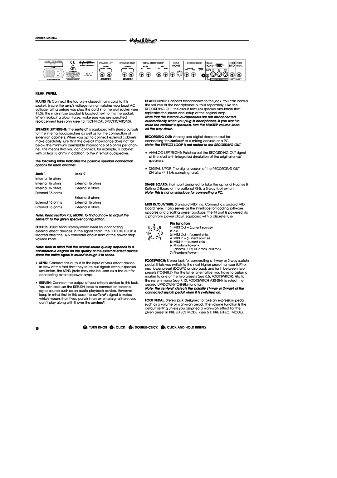
REAR PANEL
MAINS IN: Connect the
SPEAKER LEFT/RIGHT: The zenTera® is equipped with stereo outputs for the internal loudspeakers as well as for the connection of extension cabinets. When you opt to connect external cabinets, make absolutely sure that the overall impedance does not fall below the minimum permissible impedance of 6 ohms per chan- nel. This means that you can connect, for example, a cabinet with at least 8 ohms in addition to the internal loudspeaker.
The following table indicates the possible speaker connection options for each channel:
Jack 1 | Jack 2 |
Internal 16 ohms | - |
Internal 16 ohms | External 16 ohms |
Internal 16 ohms | External 8 ohms |
External 16 ohms | - |
- | External 8 ohms |
External 16 ohms | External 16 ohms |
External 16 ohms | External 8 ohms |
Note: Read section 7.2, MODE, to find out how to adjust the zenTera® to the given speaker configuration.
EFFECTS LOOP: Serial stereo/stereo insert for connecting external effect devices. In the signal chain, the EFFECTS LOOP is located after the D/A converter and in front of the power amp volume knob.
Note: Bear in mind that the overall sound quality depends to a considerable degree on the quality of the external effect device since the entire signal is routed through it in series.
•SEND: Connect this output to the input of your effect device. In view of the fact that they route out signals without speaker simulation, the SEND jacks may also be used as a line out for connecting external power amps.
•RETURN: Connect the output of your effects device to this jack. You can also use the RETURN jacks to connect an external signal source such as an audio playback device. However, keep in mind that in this case the zenTera®'s signal is muted, which means that if you patch in an external signal here, you can’t play along with it over the zenTera®.
HEADPHONES: Connect headphones to this jack. You can control the volume of the headphones output separately. Like the RECORDING OUT, this circuit features speaker simulation that replicates the sound and setup of the original amp.
Note that the internal loudspeakers are not disconnected automatically when you plug in headphones. If you want to mute the zenTera®'s speakers, turn the MASTER volume knob all the way down.
RECORDING OUT: Analog and digital stereo output for connecting the zenTera® to a mixing console or a PC.
Note: The EFFECTS LOOP is not routed to the RECORDING OUT.
•ANALOG LEFT/RIGHT: Patches out the RECORDING OUT signal at line level with integrated simulation of the original amps' speakers.
•DIGITAL S/PDIF: The digital version of the RECORDING OUT (24 bits; 44,1 kHz sampling rate).
STAGE BOARD:
Note: This is not an interface for connecting a PC.
MIDI IN/OUT/THRU: Standard MIDI trio. Connect a standard MIDI board here. It also serves as the interface for loading software updates and creating preset backups. The IN port is powered via a phantom power circuit equipped with a discrete fuse.
4 2 | 5 | Pin function |
1: MIDI Out + (current source) | ||
1 | 3 | 2: n.c. |
3: MIDI Out – (current sink) | ||
6 | 7 | 4: MIDI In + (current source) |
5:MIDI In – (current sink)
6:Phantom Power +
(approx. 11 V DC/ max. 600 mA)
7:Phantom Power -
FOOTSWITCH: Stereo jack for connecting a
Note: The zenTera® detects the polarity
FOOT PEDAL: Stereo jack designed to take an expression pedal such as a volume or
10 | W: TURN KNOB r: CLICK s: |