C15C16
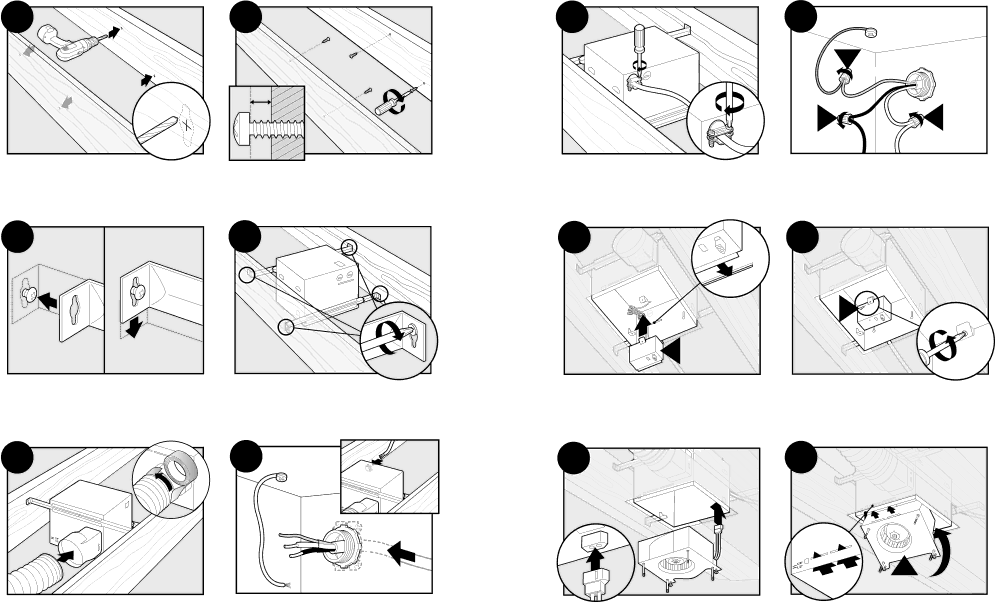
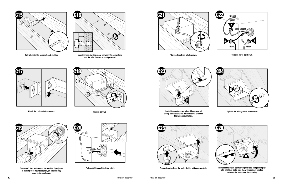
Drill a hole in the center of each outline. | Insert screws, leaving space between the screw head |
| and the joist. Screws are not provided. |
C21
Tighten the strain relief screws.
C22 | Ground |
|
| Green |
|
| A |
|
| Bare Copper | |
A |
| A |
| Black | White |
Connect wires as shown.
C17 | C18 |
Attach the rails onto the screws. | Tighten screws. |
C23 | C24 |
2 |
|
| G |
1 |
|
F |
|
Install the wiring cover plate. Make sure all | Tighten the wiring cover plate screw. |
wiring connections are inside the box or under |
|
the wiring cover plate. |
|
C25 

 C26
C26
Connect 4” duct and vent to the outside. Tape joints.
If ducting does not fit securely, an adapter may
need to be purchased.
Pull wires through the strain relief.
Connect wiring from the motor to the wiring cover plate.
H
Reinstall the motor by inserting the tabs and pushing up
into position. Make sure the wires are not pinched
between the motor and the housing.
12 | 13 |
