W A R N I N G
TO REDUCE THE RISK OF ELECTRIC SHOCK OR INJURY, OBSERVE THE FOLLOWING:
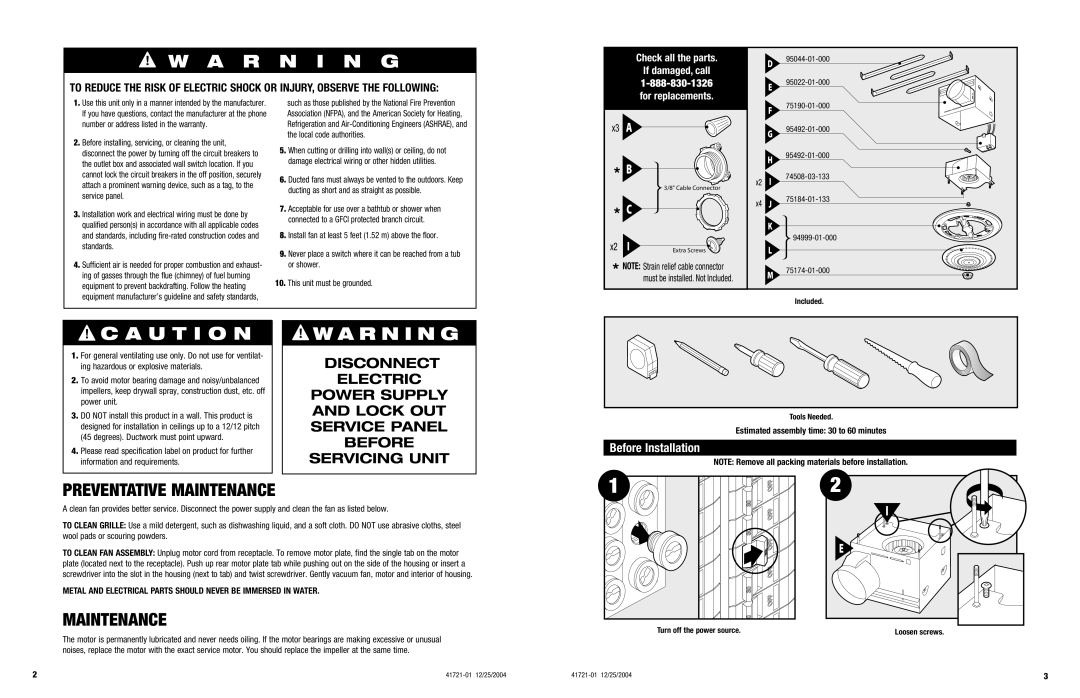
Check all the parts. If damaged, call
D95044-01-000
E95022-01-000
1. | Use this unit only in a manner intended by the manufacturer. |
| If you have questions, contact the manufacturer at the phone |
| number or address listed in the warranty. |
2. | Before installing, servicing, or cleaning the unit, |
| disconnect the power by turning off the circuit breakers to |
| the outlet box and associated wall switch location. If you |
such as those published by the National Fire Prevention Association (NFPA), and the American Society for Heating, Refrigeration and
5. When cutting or drilling into wall(s) or ceiling, do not |
damage electrical wiring or other hidden utilities. |
x3 A
F75190-01-000
G95492-01-000
H
cannot lock the circuit breakers in the off position, securely |
attach a prominent warning device, such as a tag, to the |
6. Ducted fans must always be vented to the outdoors. Keep |
ducting as short and as straight as possible. |
3/8" Cable Connector
x2
I
| service panel. |
3. | Installation work and electrical wiring must be done by |
| qualified person(s) in accordance with all applicable codes |
| and standards, including |
| standards. |
4. | Sufficient air is needed for proper combustion and exhaust- |
| ing of gasses through the flue (chimney) of fuel burning |
| equipment to prevent backdrafting. Follow the heating |
| equipment manufacturer’s guideline and safety standards, |
7. | Acceptable for use over a bathtub or shower when |
| connected to a GFCI protected branch circuit. |
8. | Install fan at least 5 feet (1.52 m) above the floor. |
9. | Never place a switch where it can be reached from a tub |
| or shower. |
10. This unit must be grounded. | |
*C
x2 I | Extra Screws |
*NOTE: Strain relief cable connector must be installed. Not Included.
x4 J
K
L
M
Included.
 C A U T I O N
1.For general ventilating use only. Do not use for ventilat- ing hazardous or explosive materials.
2.To avoid motor bearing damage and noisy/unbalanced impellers, keep drywall spray, construction dust, etc. off power unit.
3.DO NOT install this product in a wall. This product is designed for installation in ceilings up to a 12/12 pitch (45 degrees). Ductwork must point upward.
4.Please read specification label on product for further information and requirements.
![]() W A R N I N G
W A R N I N G
DISCONNECT
ELECTRIC
POWER SUPPLY AND LOCK OUT SERVICE PANEL BEFORE SERVICING UNIT
Tools Needed.
Estimated assembly time: 30 to 60 minutes
Before Installation
NOTE: Remove all packing materials before installation.
PREVENTATIVE MAINTENANCE
A clean fan provides better service. Disconnect the power supply and clean the fan as listed below.
TO CLEAN GRILLE: Use a mild detergent, such as dishwashing liquid, and a soft cloth. DO NOT use abrasive cloths, steel wool pads or scouring powders.
TO CLEAN FAN ASSEMBLY: Unplug motor cord from receptacle. To remove motor plate, find the single tab on the motor plate (located next to the receptacle). Push up rear motor plate tab while pushing out on the side of the housing or insert a screwdriver into the slot in the housing (next to tab) and twist screwdriver. Gently vacuum fan, motor and interior of housing.
METAL AND ELECTRICAL PARTS SHOULD NEVER BE IMMERSED IN WATER.
MAINTENANCE
The motor is permanently lubricated and never needs oiling. If the motor bearings are making excessive or unusual noises, replace the motor with the exact service motor. You should replace the impeller at the same time.
1 | 2 | OFF |
| 30 | OFF |
|
| |
| 30 |
|
|
| OFF |
|
| 30 |
|
| OFF |
| 30 | OFF |
|
| |
| 30 |
|
Turn off the power source.
2 |
I |
E |
Loosen screws.
2 |
3 |