SETUP AND ADJUSTMENTS
ROPS Assembly
(Roll Over Protection System)
ROPS Assembly Components
1 - Top Loop
4.Torque all 1/2” hardware to 80 ft./lbs. (110 N•m) and all 5/8” hardware to 97 ft/lbs. (131.5 N•m).
5.Install and tighten knobs against the side post.
1 - Left Side Post
1 - Right Side Post
1 - Hardware Bag
2 - 1/2” Latch Pins w/lanyard
2 - 1/2C x 3 1/4” Cap screws
2 - 1/2C Centerlock nuts
4 - 5/8C X 3” Cap screws
4 - 5/8C Centerlock nuts
8 - 5/8 Washer, flat
2 - Knobs
(all hardware Grade 5).
1.Remove roll bar and parts bag from the box.
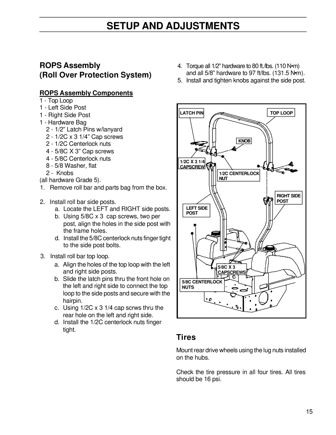
2.Install roll bar side posts.
a.Locate the LEFT and RIGHT side posts.
b.Using 5/8C x 3 cap screws, two per
post, align the holes in the side post with the frame holes.
LATCH PIN
1/2C X 3 1/4
CAPSCREW ![]()
![]()
![]()
![]()
LEFT SIDE
POST
KNOB
1/2C CENTERLOCK NUT
TOP LOOP
RIGHT SIDE
POST
d.Install the 5/8C centerlock nuts finger tight to the side post bolts.
3.Install roll bar top loop.
a.Align the holes of the top loop with the left and right side posts.
b.Slide the latch pins thru the front hole on the left and right side to connect the top loop to the side posts and secure with the hairpin.
c.Using 1/2C x 3 1/4 cap scrws thru the rear hole on the left and right side.
d.Install the 1/2C centerlock nuts finger tight.
5/8C X 3
CAPSCREWS![]()
5/8C CENTERLOCK![]()
![]()
![]()
![]()
NUTS
Tires
Mount rear drive wheels using the lug nuts installed on the hubs.
Check the tire pressure in all four tires. All tires should be 16 psi.
15
