Contents
BZ6127TD/968999262 BZ7234TD/968999264
Husqvarna All righs reserved Beatrice, NE Printed U.S.A
Index
Introduction
Introduction
Good Service
Manufacturing Number
Symbols and Decals
Symbols and Decals
Safety Instructions
Safety Instructions
General Use
Keep children away from the work area
Driving on Slopes
Do as follows
Maintenance
Children
8011-563
Transport
Important Information
Roll Over Protection System
Customer Responsibilities
Setup and Adjustments
Seat Assembly
Rops Assembly Components
Rops Assembly Roll Over Protection System
Tires
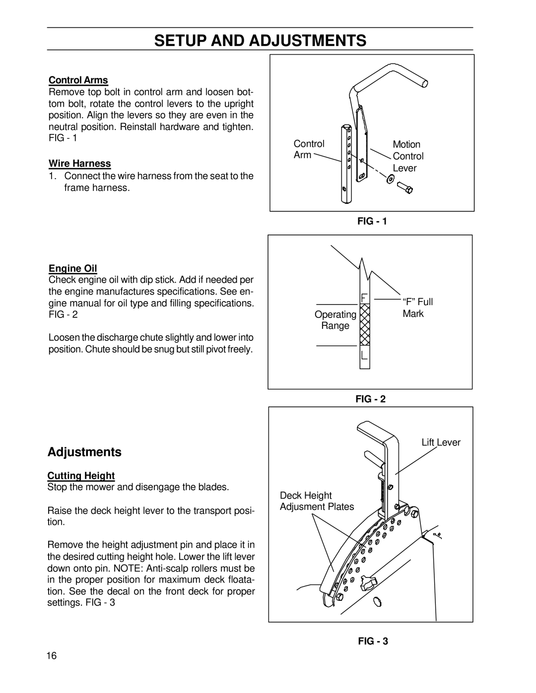
Adjustments
Wire Harness
Control Arms
Engine Oil
Mower Deck Leveling
Motion Control Linkage Adjustment
Throttle Lever Tension
Presentation
Controls
Component Locations
Gauges
Throttle Control
Ignition
Hour Meter
Engaging the Mower Deck
Seat Adjustment
Parking Brake
Motion Control Levers
Motion control levers
Hydraulic Lift Switch
Outdoors see the safety rules
Refueling
Fuel Shut-Off
Fuses
Hydraulic Lift for the Mower Deck
Manual Lifting Lever with Foot Assist for the Mower Deck
Pin must be locked into a hole for trans- port or mowing
Relays
Accessories
Tracking
Operation
Running
Before Starting
Starting the Engine
Steering controls in the outward, locked neutral position
Start position
Running
Released parking brake
Be evenly adjusted. See Maintenance
Mower deck’s anti-scalp rollers should
Mowing Tips
Transport & Extended Periods Inactivity
Stopping the Engine
Moving by Hand
Maintenance
Maintenance Schedule
Nance Maintenance Each 100 150 Before After
Checking the Safety System
Mower Deck Leveling
Clutch Service and Maintenance
Checking and Adjusting the Throttle Cable
Checking the Engine’s Cooling Air Intake
Replacing the Air Filter
Checking Tire Pressures
Replacing the Fuel Filter
Check and Filling Coolant System
Checking the Parking Brake
Overflow bottle Parking brake in the disengaged position
Cleaning and Washing
Checking the Blades
Checking Battery
Penetrate the skin, causing seri
Checking the Hydraulic System
125 gal
Caster Wheels
Motion Control Linkage Adjustment
Keep hands, feet and clothing away from rotating tires
Deck Lift Power Unit
Cutter Housings
Mule Drive System Adjustment
Lubrication
Lubrication
Lubrication Schedule
Lubricating the Cables
Lubricating in Accordance with the Lubrication Schedule
Hydraulic System, Oil Level
Driver’s Seat
Engine Oil Changing the Engine Oil
Throttle Cable, Lever Bearings
Front Wheel Mount
Belt Adjuster, Mower Deck
Front Wheel Bearings
Steering Control Shafts
Belt Adjuster Mule Drive Idler Arm
Mower Deck Struts
Belt Adjuster, Hydraulic Pumps
Trouble Shooting Guide
Trouble Shooting Guide
Problem Cause
Trouble Shooting Guide
Trouble Shooting Guide
Service
Storage
Storage
Winter Storage
Technical Data
Technical Data
Measurements, Weights, Etc
Engine
Clutch
Noise Emissions and Cutting Width
Electrical System
Transmission
Service Journal
Service Journal
Delivery Service
Action Date, mtr reading, stamp, sign
After the First 50 Hours
Daily
Hour Service
Service Journal
Service Journal
Service Journal
At Least Once Each Year
Page
110889R0208/11/05

![]()
![]()
![]() “F” Full
“F” Full![]() Mark
Mark