MAINTENANCE
Motion Control Linkage Adjustment
This adjustment must be made with the rear wheels rotating. Raise the rear of the machine and block it up so the wheels are free to rotate
WARNING!
Keep hands, feet and clothing away from rotating tires.
Place a 2 x 4 board between the foot plate and the center of the seat to engage the seat safety switch.
1
A
2
3
C
D B
4
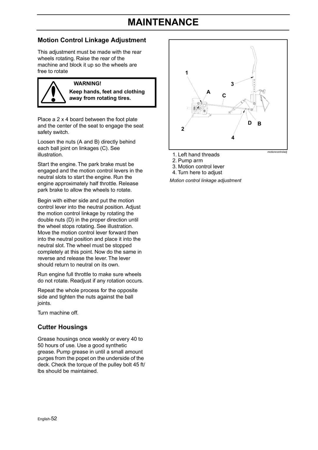
Loosen the nuts (A and B) directly behind each ball joint on linkages (C). See illustration.
Start the engine. The park brake must be
1. Left hand threads
2. Pump arm
motioncontroladj
engaged and the motion control levers in the neutral slots to start the engine. Run the engine approximately half throttle. Release park brake to allow the wheels to rotate.
Begin with either side and put the motion control lever into the neutral position. Adjust the motion control linkage by rotating the double nuts (D) in the proper direction until the wheel stops rotating. See illustration. Move the motion control lever forward then into the neutral position and place it into the neutral slot. The wheel must be stopped completely at this point. Now do the same in reverse and release the lever. The lever should return to neutral on its own.
Run engine full throttle to make sure wheels do not rotate. Readjust if any rotation occurs.
Repeat the whole process for the opposite side and tighten the nuts against the ball joints.
Turn machine off.
Cutter Housings
Grease housings once weekly or every 40 to 50 hours of use. Use a good synthetic grease. Pump grease in until a small amount purges from the popet on the underside of the deck. Check the torque of the pulley bolt 45 ft/ lbs should be maintained.
3. Motion control lever
4. Turn here to adjust Motion control linkage adjustment
