Rev. 0508
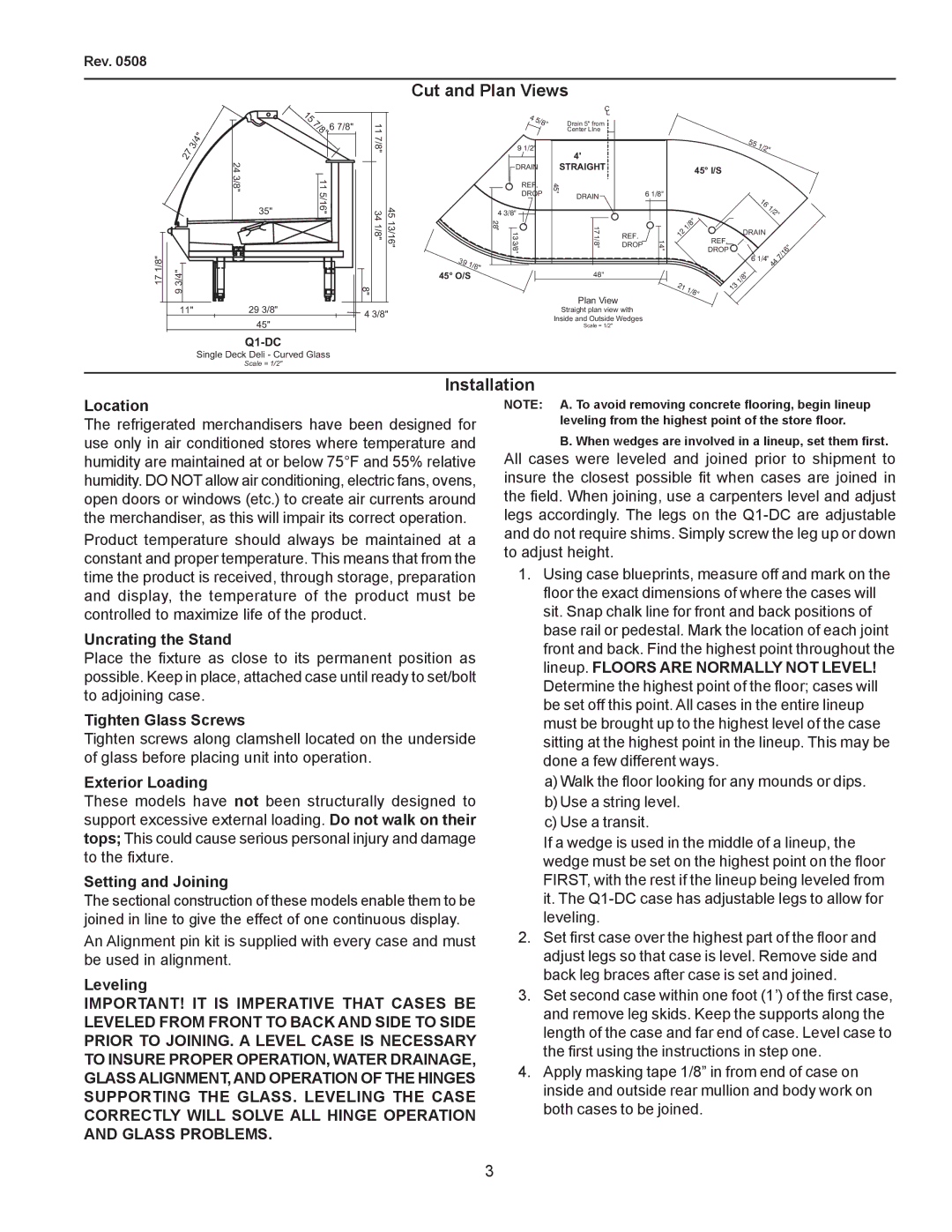
Cut and Plan Views
27 | 3/4" |
|
17 1/8" | 3/4" |
| 9 |
11"
24 3/8"
35"
293/8"
45"
15 |
|
7/8" | 6 7/8" |
11 5/16" |
|
11 7/8" |
|
34 1/8" | 45 13/16" |
39 | 1/8" |
|
45° O/S
8"
4 3/8"
4 | 5/8" |
|
9 1/2"
DRAIN
REF.
DROP
4 3/8"
28 "
13 3/8"
C
L
Drain 5" from
Center LIne
4'
STRAIGHT
45" |
| 6 1/8" | |
DRAIN |
| ||
|
| ||
17 | REF. |
| |
1/8" | 14 | ||
DROP | |||
| " |
48"
Plan View
Straight plan view with Inside and Outside Wedges
Scale = 1/2"
45° I/S
| " |
|
| /8 |
|
1 |
| |
2 |
|
|
1 |
| REF. |
|
| |
|
| DROP |
21 | 1/8" |
|
551/2"
16
1/2"
DRAIN
|
|
| 6" |
6 1/4" |
| 1 | |
44 | 7/ |
| |
|
|
| |
131/8"
Single Deck Deli - Curved Glass
Scale = 1/2"
Installation
Location
The refrigerated merchandisers have been designed for use only in air conditioned stores where temperature and humidity are maintained at or below 75°F and 55% relative humidity. DO NOT allow air conditioning, electric fans, ovens, open doors or windows (etc.) to create air currents around the merchandiser, as this will impair its correct operation.
Product temperature should always be maintained at a constant and proper temperature. This means that from the time the product is received, through storage, preparation and display, the temperature of the product must be controlled to maximize life of the product.
Uncrating the Stand
Place the fixture as close to its permanent position as possible. Keep in place, attached case until ready to set/bolt to adjoining case.
Tighten Glass Screws
Tighten screws along clamshell located on the underside of glass before placing unit into operation.
Exterior Loading
These models have not been structurally designed to support excessive external loading. Do not walk on their tops; This could cause serious personal injury and damage to the fixture.
Setting and Joining
The sectional construction of these models enable them to be joined in line to give the effect of one continuous display.
An Alignment pin kit is supplied with every case and must be used in alignment.
Leveling
IMPORTANT! IT IS IMPERATIVE THAT CASES BE LEVELED FROM FRONT TO BACK AND SIDE TO SIDE PRIOR TO JOINING. A LEVEL CASE IS NECESSARY TO INSURE PROPER OPERATION, WATER DRAINAGE, GLASS ALIGNMENT, AND OPERATION OF THE HINGES SUPPORTING THE GLASS. LEVELING THE CASE CORRECTLY WILL SOLVE ALL HINGE OPERATION AND GLASS PROBLEMS.
NOTE: A. To avoid removing concrete flooring, begin lineup leveling from the highest point of the store floor.
B. When wedges are involved in a lineup, set them first.
All cases were leveled and joined prior to shipment to insure the closest possible fit when cases are joined in the field. When joining, use a carpenters level and adjust legs accordingly. The legs on the
1.Using case blueprints, measure off and mark on the floor the exact dimensions of where the cases will sit. Snap chalk line for front and back positions of base rail or pedestal. Mark the location of each joint front and back. Find the highest point throughout the lineup. FLOORS ARE NORMALLY NOT LEVEL!
Determine the highest point of the floor; cases will be set off this point. All cases in the entire lineup must be brought up to the highest level of the case sitting at the highest point in the lineup. This may be done a few different ways.
a)Walk the floor looking for any mounds or dips.
b)Use a string level.
c)Use a transit.
If a wedge is used in the middle of a lineup, the wedge must be set on the highest point on the floor FIRST, with the rest if the lineup being leveled from it. The
2.Set first case over the highest part of the floor and adjust legs so that case is level. Remove side and back leg braces after case is set and joined.
3.Set second case within one foot (1’) of the first case, and remove leg skids. Keep the supports along the length of the case and far end of case. Level case to the first using the instructions in step one.
4.Apply masking tape 1/8” in from end of case on inside and outside rear mullion and body work on both cases to be joined.