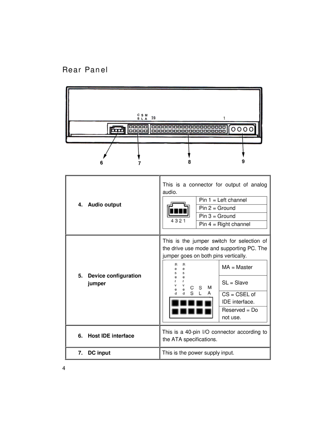
Rear Panel
4. Audio output
5.Device configuration jumper
6.Host IDE interface
7.DC input
This is a connector for output of analog audio.
Pin 1 = Left channel
Pin 2 = Ground
Pin 3 = Ground
Pin 4 = Right channel
This is the jumper switch for selection of the drive use mode and supporting PC. The jumper goes on both pins vertically.
MA = Master
SL = Slave
CS = CSEL of
IDE interface.
Reserved = Do not use.
This is a
![]()
![]() This is the power supply input.
This is the power supply input.
4