3.2.1 Light Path diagnostics
The Models 6C1 and 6E1 are the first IBM UNIX servers that implement Light Path diagnostics technology. Light Path LEDs provide an obvious and intuitive means to positively identify the failing Field Replaceable Unit (FRU) through a path of light emitting points, starting on the exterior of the system (System Attention LED), located on the front of the system (also on the rear of rack mounted 6C1), and ending with a LED at or near the failing FRU. Correlation of the LED layout and the failing component is straightforward. Intermediate light points lead you to the area or subassembly of the machine where the failing FRU is located.
Initially, for the Models 6C1 and 6E1, the fault LEDs will be implemented with only two LED states (ON and OFF).
Attention and Light Path LEDs
The attention and Light Path LEDs provide a means to identify failing components in your server. Attention LEDs are located on the front and rear of the system to make it easy for an
When a failing component is detected in your server, the attention LED is turned on. To further help you identify the failing component, go to the indicator panel inside the server and check which LEDs are lit on the indicator panel. After you have replaced the failing part you have to manually turn off the attention light using the service processor submenu or invoke the online diagnostics with the diag command (as discussed in the following).
Enter diag and press Enter to continue. Then from the Function Selection main menu select Task Selection (Diagnostics, Advanced Diagnostics, Service Aids, etc.). Scroll down and select Log Repair Action. Select the device that was repaired (if the device is not listed, select sysplanar0). This will turn off the attention and Light Path LEDs. For more detailed information refer to the IBM ^pSeries 610 Models 6C1 and 6E1 User’s Guide,
System indicator panel
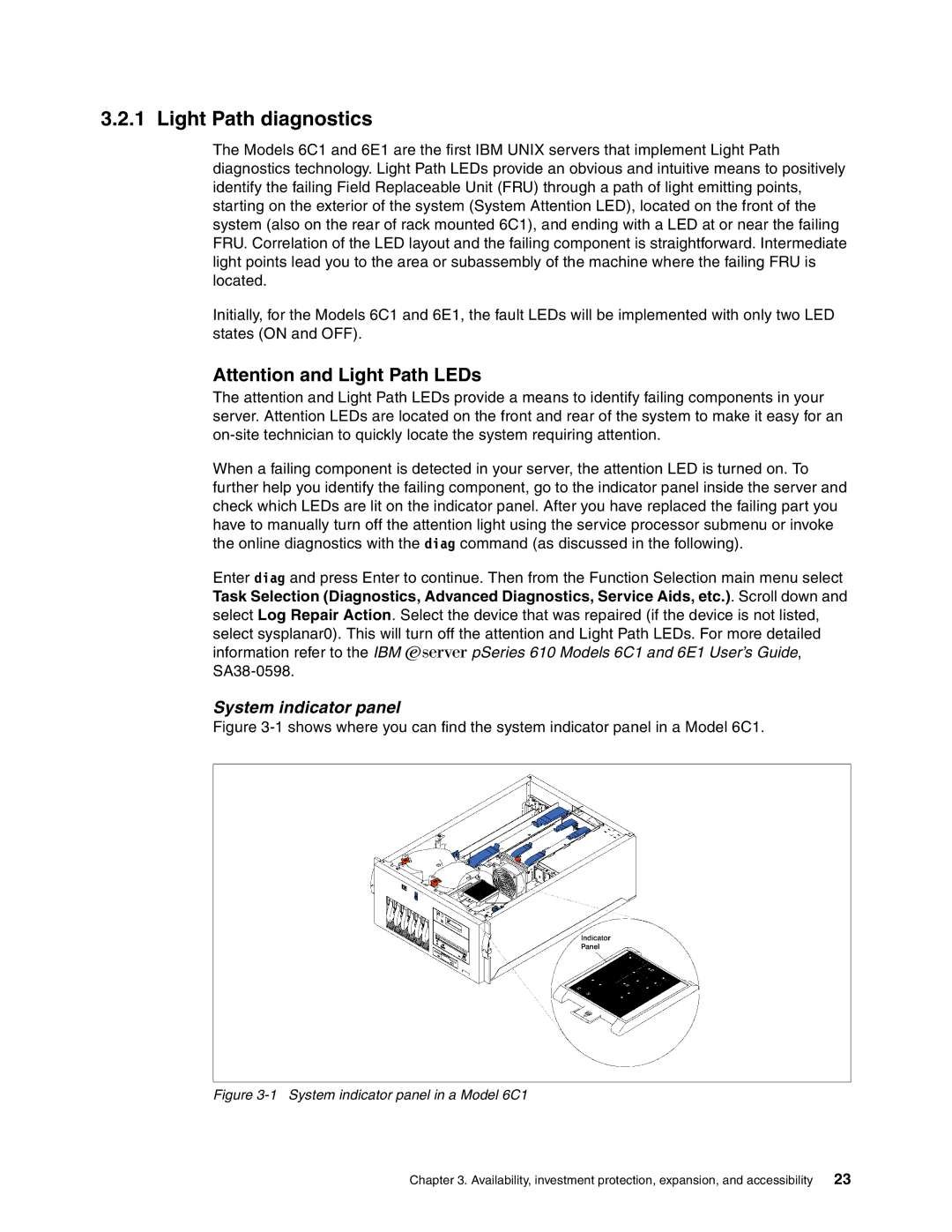
Figure 3-1 shows where you can find the system indicator panel in a Model 6C1.
Figure 3-1 System indicator panel in a Model 6C1
Chapter 3. Availability, investment protection, expansion, and accessibility | 23 |
