![]()
![]()
![]() P8SC8/P8SCi User's Manual
P8SC8/P8SCi User's Manual
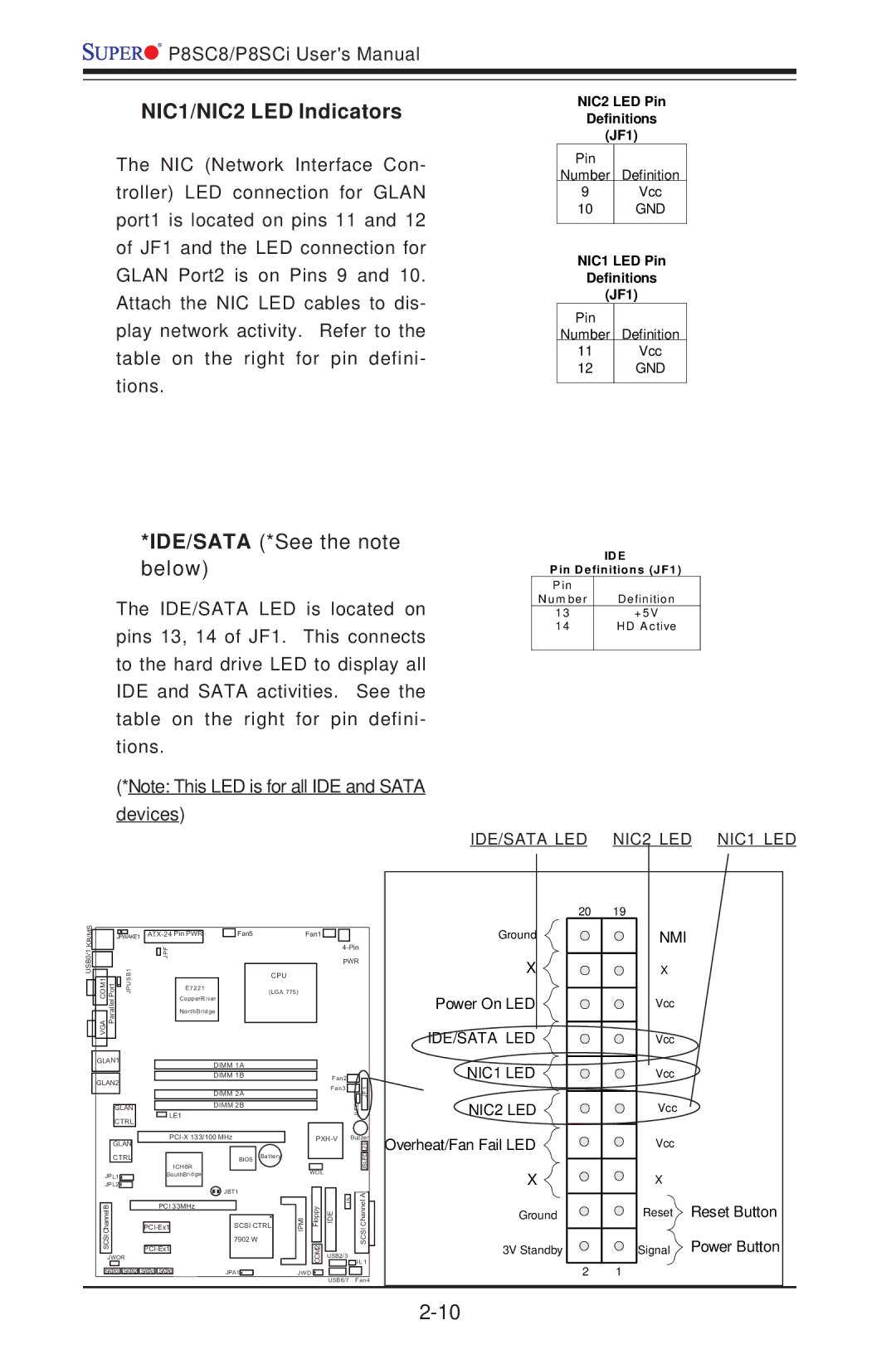
NIC1/NIC2 LED Indicators
NIC2 LED Pin
Definitions
(JF1)
The NIC (Network Interface Con- troller) LED connection for GLAN port1 is located on pins 11 and 12 of JF1 and the LED connection for GLAN Port2 is on Pins 9 and 10. Attach the NIC LED cables to dis- play network activity. Refer to the table on the right for pin defini- tions.
Pin
Number Definition
9Vcc
10 GND
NIC1 LED Pin
Definitions
(JF1)
Pin
Number Definition
11Vcc
12GND
*IDE/SATA (*See the note below)
The IDE/SATA LED is located on pins 13, 14 of JF1. This connects to the hard drive LED to display all IDE and SATA activities. See the table on the right for pin defini- tions.
(*Note: This LED is for all IDE and SATA devices)
ID E
P in D efinitions (JF1)
P in |
|
N u m be r | D e fin ition |
1 3 | + 5 V |
1 4 | H D A ctive |
|
|
IDE/SATA LED NIC2 LED NIC1 LED
USB0/1 KB/MS
| JPWAKE1 |
| Fan5 | Fan1 | |||
|
|
|
| JPF |
|
| |
|
|
|
|
|
| ||
|
|
|
|
|
|
|
|
VGACOM1 PortParallel | B1 |
|
|
|
| CPU | |
PJUS |
| E7221 |
| (LGA 775) | |||
|
|
|
|
|
|
| |
|
|
|
| CopperRiver |
|
| |
|
|
|
| NorthBridge |
|
| |
20 19
Ground
X ![]()
![]()
![]()
Power On LED
IDE/SATA LED
NMI
X
Vcc
Vcc
GLAN1 | DIMM 1A |
|
| NIC1 LED |
|
|
|
| Vcc | ||
GLAN2 | DIMM 1B | Fan2 |
| ||
| Fan3 |
| 1 |
| |
|
|
|
| ||
| DIMM 2A |
| JLED | FJ | Vcc |
| LE1 |
| NIC2 LED | ||
GLAN | DIMM 2B |
|
|
|
|
CTRL |
|
|
|
|
|
Buzzer | |||
GLAN |
|
| 9 |
|
|
| J |
Overheat/Fan Fail LED
Vcc
CTRL |
|
|
|
|
| ||
|
|
|
|
|
| ICH6R | |
JPL1 |
|
| SouthBridge | ||||
JPL2 |
|
|
|
|
|
|
|
B |
|
|
| PCI 33MHz |
| ||
|
|
|
| ||||
Channel |
|
|
|
|
|
| |
|
|
|
|
| |||
SCSI |
|
|
| ||||
|
|
|
| ||||
JWOR |
|
|
SATA3 SATA2 | SATA1 | SATA0 |
BIOS | Battery |
|
WOL
JBT1
JBT1
SCSI CTRL | IMIP | ypplo F |
7902 W |
| 2MO C |
|
| |
JPA1 | J W D |
|
![]() 5J EID
5J EID
USB2/3
USB6/7
JSLED
CS CIS ah nn Ale
J L 1
Fan4
X
Ground
3V Standby
X
Reset Reset Button
Signal Power Button
2 1