Chapter 2: Installation
Reset Connector
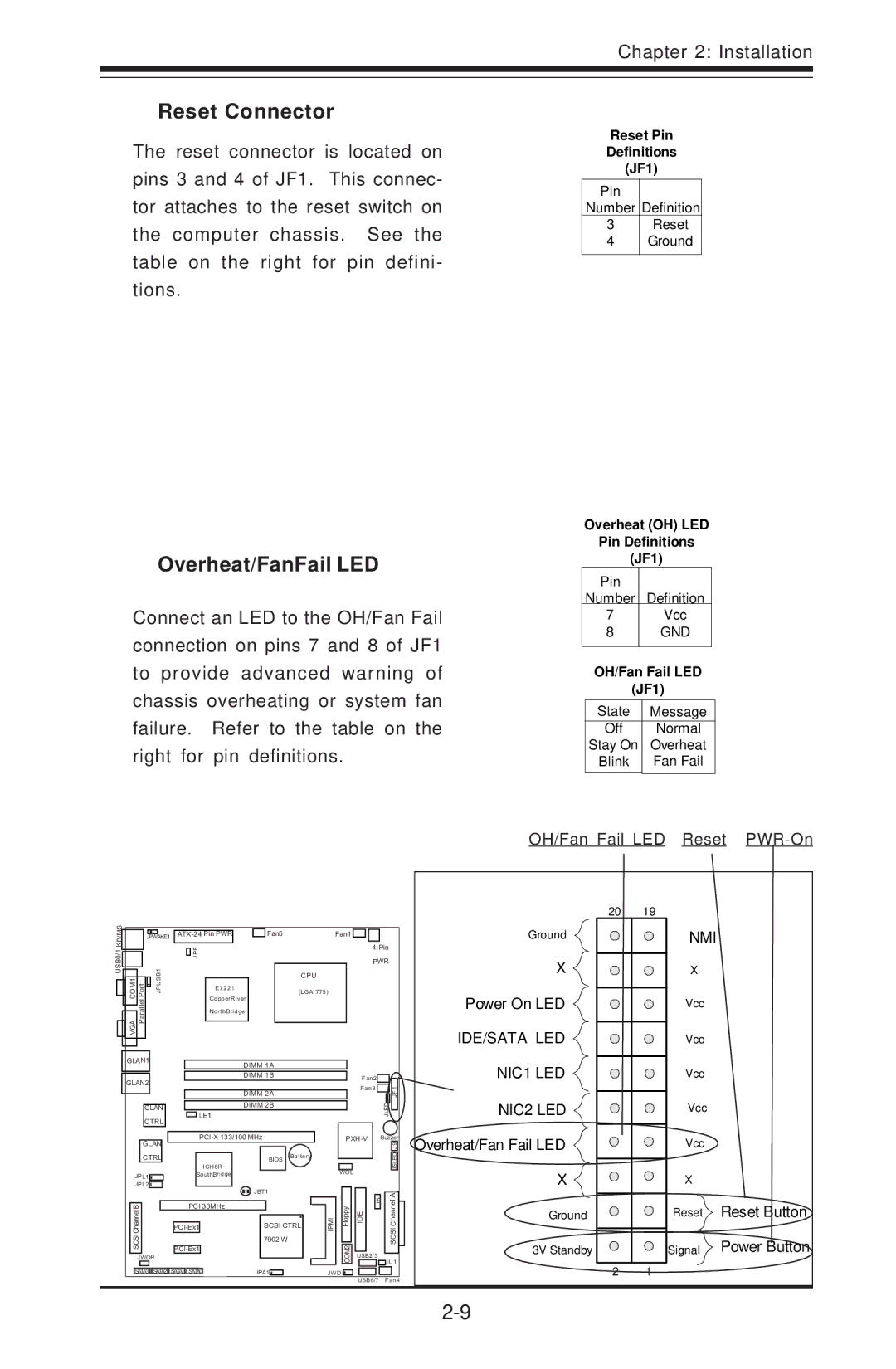
The reset connector is located on pins 3 and 4 of JF1. This connec- tor attaches to the reset switch on the computer chassis. See the table on the right for pin defini- tions.
Overheat/FanFail LED
Connect an LED to the OH/Fan Fail connection on pins 7 and 8 of JF1 to provide advanced warning of chassis overheating or system fan failure. Refer to the table on the right for pin definitions.
Reset Pin
Definitions
(JF1)
Pin
Number Definition
3Reset
4Ground
Overheat (OH) LED
Pin Definitions
(JF1)
Pin
Number Definition
7Vcc
8GND
OH/Fan Fail LED
(JF1)
State | Message |
Off | Normal |
Stay On | Overheat |
Blink | Fan Fail |
|
|
OH/Fan Fail LED Reset PWR-On
USB0/1 KB/MS
| JPWAKE1 |
| Fan5 | Fan1 | |||
|
|
|
| JPF |
|
| |
|
|
|
|
|
| ||
|
|
|
|
|
|
|
|
VGACOM1 PortParallel | B1 |
|
|
|
| CPU | |
PJUS |
| E7221 |
| (LGA 775) | |||
|
|
|
|
|
|
| |
|
|
|
| CopperRiver |
|
| |
|
|
|
| NorthBridge |
|
| |
20 19
Ground
X ![]()
![]()
![]()
Power On LED
IDE/SATA LED
NMI
X
Vcc
Vcc
GLAN1 | DIMM 1A |
|
| NIC1 LED |
|
|
|
| Vcc | ||
GLAN2 | DIMM 1B | Fan2 |
| ||
| Fan3 |
| 1 |
| |
|
|
|
| ||
| DIMM 2A |
| JLED | FJ | Vcc |
| LE1 |
| NIC2 LED | ||
GLAN | DIMM 2B |
|
|
|
|
CTRL |
|
|
|
|
|
Buzzer | |||
GLAN |
|
| 9 |
|
|
| J |
Overheat/Fan Fail LED
Vcc
CTRL |
|
|
|
|
| ||
|
|
|
|
|
| ICH6R | |
JPL1 |
|
| SouthBridge | ||||
JPL2 |
|
|
|
|
|
|
|
B |
|
|
| PCI 33MHz |
| ||
|
|
|
| ||||
Channel |
|
|
|
|
|
| |
|
|
|
|
| |||
SCSI |
|
|
| ||||
|
|
|
| ||||
JWOR |
|
|
SATA3 SATA2 | SATA1 | SATA0 |
BIOS | Battery |
|
WOL
JBT1
JBT1
SCSI CTRL | IMIP | ypplo F |
7902 W |
| 2MO C |
|
| |
JPA1 | J W D |
|
![]() 5J EID
5J EID
USB2/3
USB6/7
JSLED
CS CIS ah nn Ale
J L 1
Fan4
X
Ground
3V Standby
X
Reset Reset Button
Signal Power Button
2 1
