Chapter 2: Installation
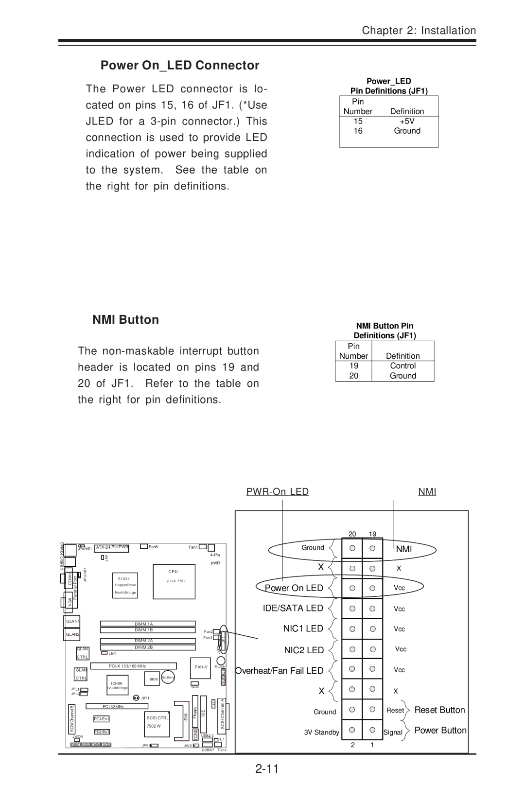
Power On_LED Connector
The Power LED connector is lo- cated on pins 15, 16 of JF1. (*Use JLED for a
NMI Button
The
PWR-On LED
Power_LED
Pin Definitions (JF1)
Pin
Number Definition
15+5V
16Ground
NMI Button Pin
Definitions (JF1)
Pin
Number Definition
19Control
20Ground
NMI
USB0/1 KB/MS
| JPWAKE1 |
| Fan5 | Fan1 | |||
|
|
|
| JPF |
|
| |
|
|
|
|
|
| ||
|
|
|
|
|
|
|
|
VGACOM1 PortParallel | B1 |
|
|
|
| CPU | |
PJUS |
| E7221 |
| (LGA 775) | |||
|
|
|
|
|
|
| |
|
|
|
| CopperRiver |
|
| |
|
|
|
| NorthBridge |
|
| |
20 19
Ground
X ![]()
![]()
![]()
Power On LED
IDE/SATA LED
NMI
X
Vcc
Vcc
GLAN1 | DIMM 1A |
|
| NIC1 LED |
|
|
|
| Vcc | ||
GLAN2 | DIMM 1B | Fan2 |
| ||
| Fan3 |
| 1 |
| |
|
|
|
| ||
| DIMM 2A |
| JLED | FJ | Vcc |
| LE1 |
| NIC2 LED | ||
GLAN | DIMM 2B |
|
|
|
|
CTRL |
|
|
|
|
|
Buzzer | |||
GLAN |
|
| 9 |
|
|
| J |
Overheat/Fan Fail LED
Vcc
CTRL |
|
|
|
|
| ||
|
|
|
|
|
| ICH6R | |
JPL1 |
|
| SouthBridge | ||||
JPL2 |
|
|
|
|
|
|
|
B |
|
|
| PCI 33MHz |
| ||
|
|
|
| ||||
Channel |
|
|
|
|
|
| |
|
|
|
|
| |||
SCSI |
|
|
| ||||
|
|
|
| ||||
JWOR |
|
|
SATA3 SATA2 | SATA1 | SATA0 |
BIOS | Battery |
|
WOL
JBT1
JBT1
SCSI CTRL | IMIP | ypplo F |
7902 W |
| 2MO C |
|
| |
JPA1 | J W D |
|
![]() 5J EID
5J EID
USB2/3
USB6/7
JSLED
CS CIS ah nn Ale
J L 1
Fan4
X
Ground
3V Standby
X
Reset Reset Button
Signal Power Button
2 1