Appendix | A. Connector pin | assignments |
|
|
| |||
|
|
|
|
|
|
|
| |
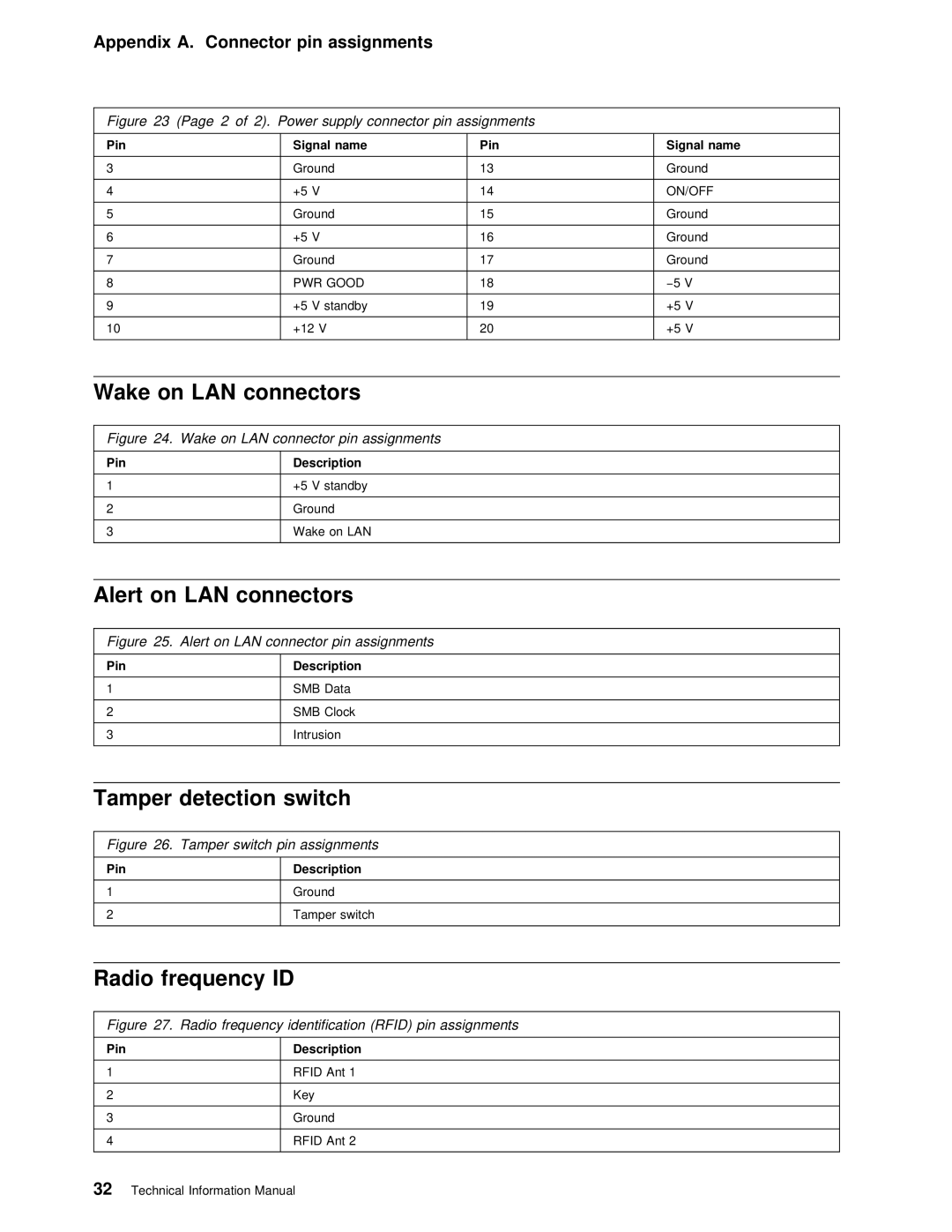
Figure | 23 | (Page 2 | of | 2). Power supply connector pin assignments |
|
| ||
|
|
|
|
|
|
|
| |
Pin |
|
| Signal | name | Pin | Signal | name | |
|
|
|
|
|
|
| ||
3 |
|
| Ground |
| 13 | Ground | ||
|
|
|
|
|
|
|
| |
4 |
|
| +5 | V |
| 14 | ON/OFF | |
|
|
|
|
|
|
| ||
5 |
|
| Ground |
| 15 | Ground | ||
|
|
|
|
|
|
|
| |
6 |
|
| +5 | V |
| 16 | Ground | |
|
|
|
|
|
|
| ||
7 |
|
| Ground |
| 17 | Ground | ||
|
|
|
|
|
|
|
| |
8 |
|
| PWR | GOOD | 18 | −5 | V | |
|
|
|
|
|
|
|
|
|
9 |
|
| +5 | V | standby | 19 | +5 | V |
|
|
|
|
|
|
|
| |
10 |
|
| +12 | V | 20 | +5 | V | |
|
|
|
|
|
|
|
|
|
|
|
|
|
|
|
|
|
|
Wake on | LAN | connectors |
|
|
|
|
| |
|
|
|
|
|
| |||
Figure | 24. | Wake on LAN connector pin assignments |
|
|
| |||
Pin
1
2
3
Description
+5 V standby
Ground
Wake on LAN
Alert on LAN connectors
Figure 25. Alert on LAN connector pin assignments
Pin
1
2
3
Description
SMB Data
SMB Clock
Intrusion
Tamper detection switch
Figure 26. Tamper switch pin assignments
Pin
1
2
Description
Ground
Tamper switch
Radio frequency | ID |
|
| |
|
|
| ||
Figure 27. | Radio frequency identification (RFID) pin assignments | |||
|
|
|
| |
Pin |
| Description |
| |
|
|
|
|
|
1 |
| RFID | Ant | 1 |
|
|
|
|
|
2 |
| Key |
|
|
|
|
|
|
|
3 |
| Ground |
|
|
|
|
|
|
|
4 |
| RFID | Ant | 2 |
|
|
|
|
|
32 Technical Information Manual