Appendix A. Connector pin assignments
SCSI high | frequency LED connectors |
|
|
Figure | 28. SCSI high frequency LED connector pin assignments |
Pin
1
2
3
4
Description
Not connected
to LED
to LED
Not connected
CD audio connector
Figure 29. CD audio connector pin assignments
Pin
1
2
3
4
Description
CD in left
CD in Ground
CD in Ground
CD in Right
USB port connectors
1 2
3 4
Figure 30. USB port connector pin assignments
Pin
1
2
3
4
Signal
VCC
+Data
Ground
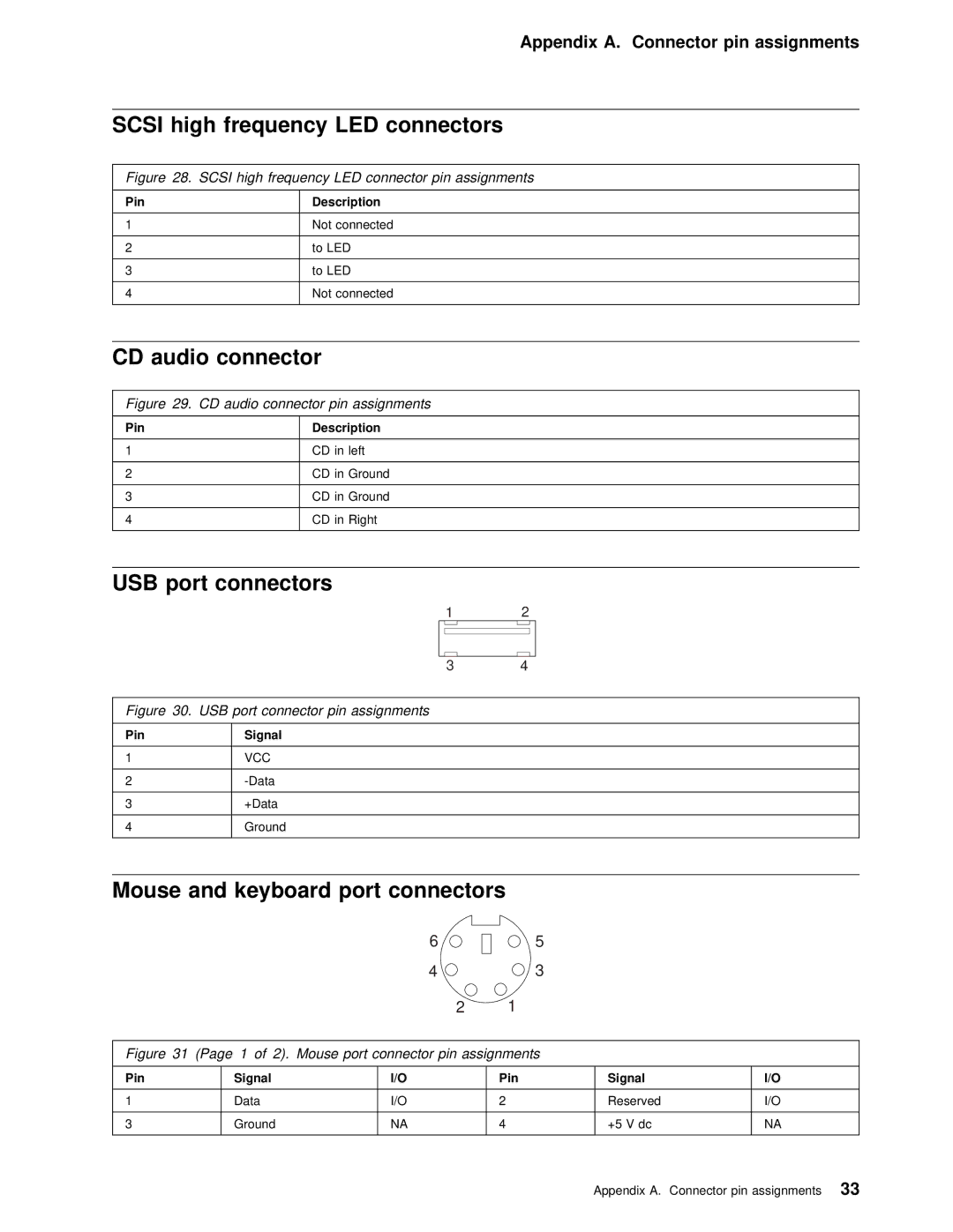
Mouse and | keyboard | port | connectors |
|
|
|
| ||
|
|
|
| 6 |
| 5 |
|
| |
|
|
|
| 4 |
| 3 |
|
| |
|
|
|
| 2 | 1 |
|
|
| |
|
|
|
|
|
|
|
|
| |
Figure | 31 (Page | 1 of | 2). Mouse port connector pin assignments |
| |||||
|
|
|
|
|
|
|
|
|
|
Pin |
| Signal |
|
| I/O | Pin |
| Signal | I/O |
|
|
|
|
|
|
|
|
|
|
1 |
| Data |
|
| I/O | 2 |
| Reserved | I/O |
|
|
|
|
|
|
|
|
|
|
3 |
| Ground |
|
| NA | 4 |
| +5 V dc | NA |
|
|
|
|
|
|
|
|
|
|
Appendix A. Connector pin assignments33