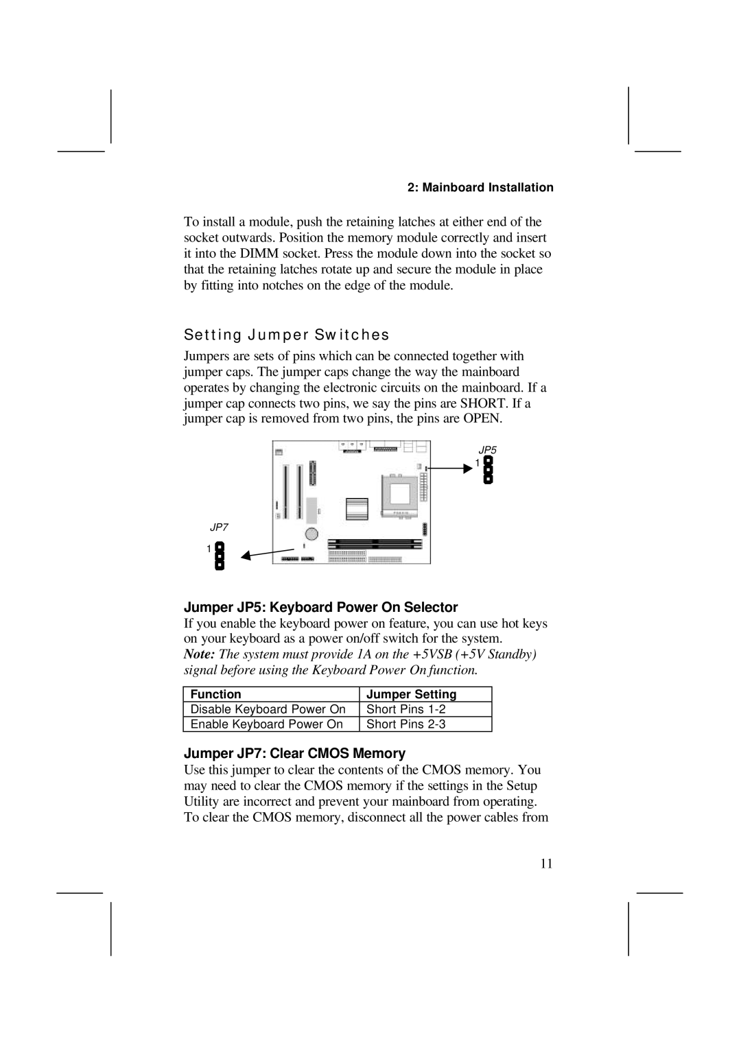
MS7308D/E, V1.6 S63X/JUNE 2000 specifications
IBM V1.6 S63X, released in June 2000, represents a significant update in the line of IBM's advanced technology solutions, particularly aimed at enhancing processing capabilities and streamlining data management. This version introduces crucial hardware and software improvements that enable organizations to operate more efficiently in an increasingly digital landscape.One of the main features of the IBM V1.6 S63X is its enhanced performance metrics. Equipped with advanced processing units, the system supports higher clock speeds, allowing for faster data processing. This increased processing power is crucial in today’s data-driven world, where real-time analysis is often necessary for competitive advantage. The S63X architecture is designed to handle complex computations and large datasets seamlessly.
In terms of memory and storage, the MS7308D/E component is noteworthy. This element is tailored for scalability, allowing organizations to expand their storage capabilities as their data needs grow. The support for various memory types ensures that the system can manage multiple workloads efficiently, which is particularly important for businesses with fluctuating data demands. Furthermore, the integration of RAID technology provides improved data redundancy and performance, ensuring that critical information is protected while enhancing access speeds.
The IBM V1.6 S63X is built with advanced networking capabilities as well. Its integrated support for high-speed Ethernet ensures robust connectivity, allowing for fast and reliable data transfer across networked systems. This is particularly beneficial for enterprises looking to streamline their operations and improve communication between departments.
Security is another focus of the IBM V1.6 S63X. Enhanced encryption algorithms and access control features are integrated into the system to safeguard sensitive information. As businesses increasingly turn to digital solutions, data protection has become paramount, making these security features a significant selling point of this IBM model.
Another characteristic of this version is its user-friendly interface, designed to facilitate better user experience. With intuitive navigation and customizable dashboards, users can easily manage tasks and access information without extensive training, reducing operational downtime.
In conclusion, IBM V1.6 S63X, MS7308D/E stands out with its powerful processing capabilities, robust memory options, advanced networking features, and strong security protocols. These attributes make it an appealing choice for organizations looking to enhance their IT infrastructure, enabling them to meet the demands of modern business effectively.

