IC-910H specifications
The Icom IC-910H is a highly regarded and versatile transceiver that is designed for amateur radio operators who are particularly interested in V/UHF and microwave communications. Known for its exceptional performance, the IC-910H encompasses a suite of features that make it a standout choice for both casual and dedicated hams.One of the main features of the IC-910H is its dual-band capability, allowing for simultaneous operation on both 144 MHz (2 meters) and 430 MHz (70 centimeters) bands. This dual operation enables users to engage in various communication modes, including SSB, CW, FM, and digital. Its high frequency stability ensures that users can rely on the transceiver for accurate and consistent transmissions.
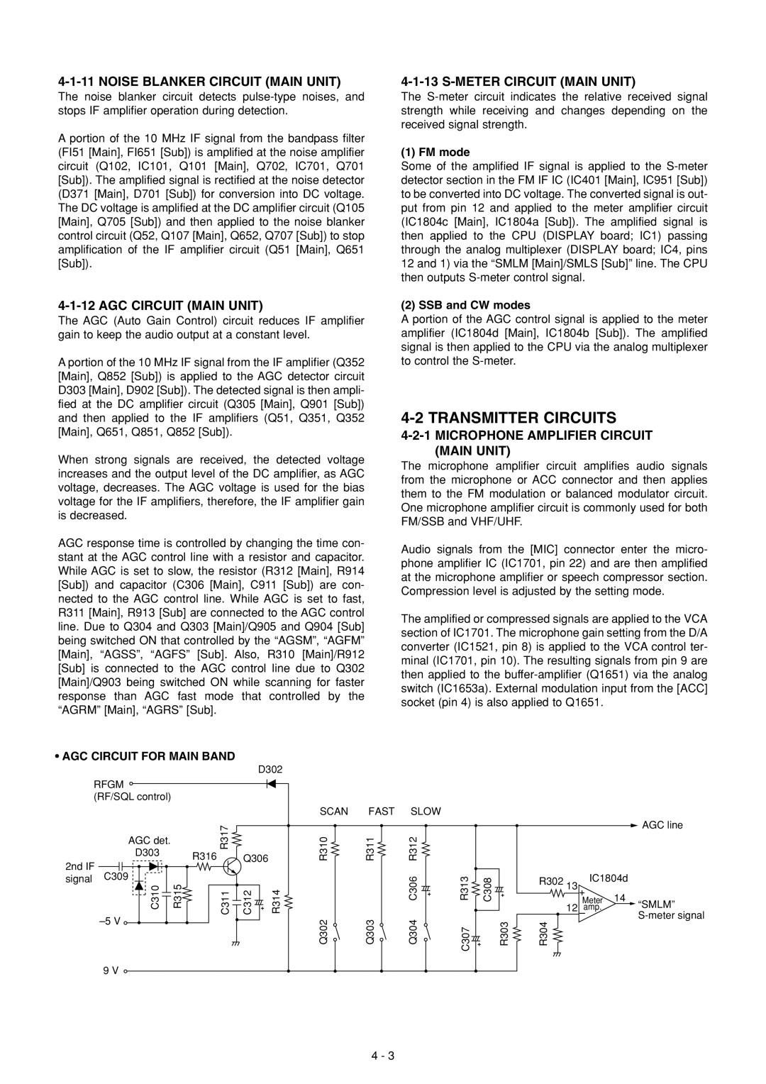
The IC-910H is equipped with a high-performance 10 MHz IF filter that improves selectivity and reduces adjacent channel interference. The optional 1.2 GHz module enhances the transceiver’s capabilities, allowing operators to venture into microwave frequencies. This expandability is a significant advantage for users who wish to progress in their amateur radio pursuits.
Another notable aspect of the IC-910H is its large, easy-to-read LCD display, which features various color options for enhanced visibility. The front panel layout is user-friendly, providing quick access to important controls and functions. The built-in DSP (Digital Signal Processing) technology offers noise reduction and filtering capabilities, significantly improving overall audio quality and making weak signals more intelligible.
The transceiver also includes extensive memory functions, with up to 1,000 memory channels available for storing frequencies, modes, and operational settings. Additionally, it supports CTCSS and DCS tones, which facilitate the use of repeater systems and private group communications.
In terms of build quality, the IC-910H features a robust construction designed for durability and long-term use. Its efficient power supply management ensures excellent performance while minimizing heat generation, making it suitable for extended operating sessions.
Overall, the Icom IC-910H is a powerful and feature-rich transceiver that is favored by many amateur radio enthusiasts. With its versatile operating modes, advanced filtering capabilities, and clear display, it stands out as a reliable tool for both casual operators and serious DXers. Its well-thought-out design and comprehensive features make it a valuable addition to any ham's station collection.

