22`

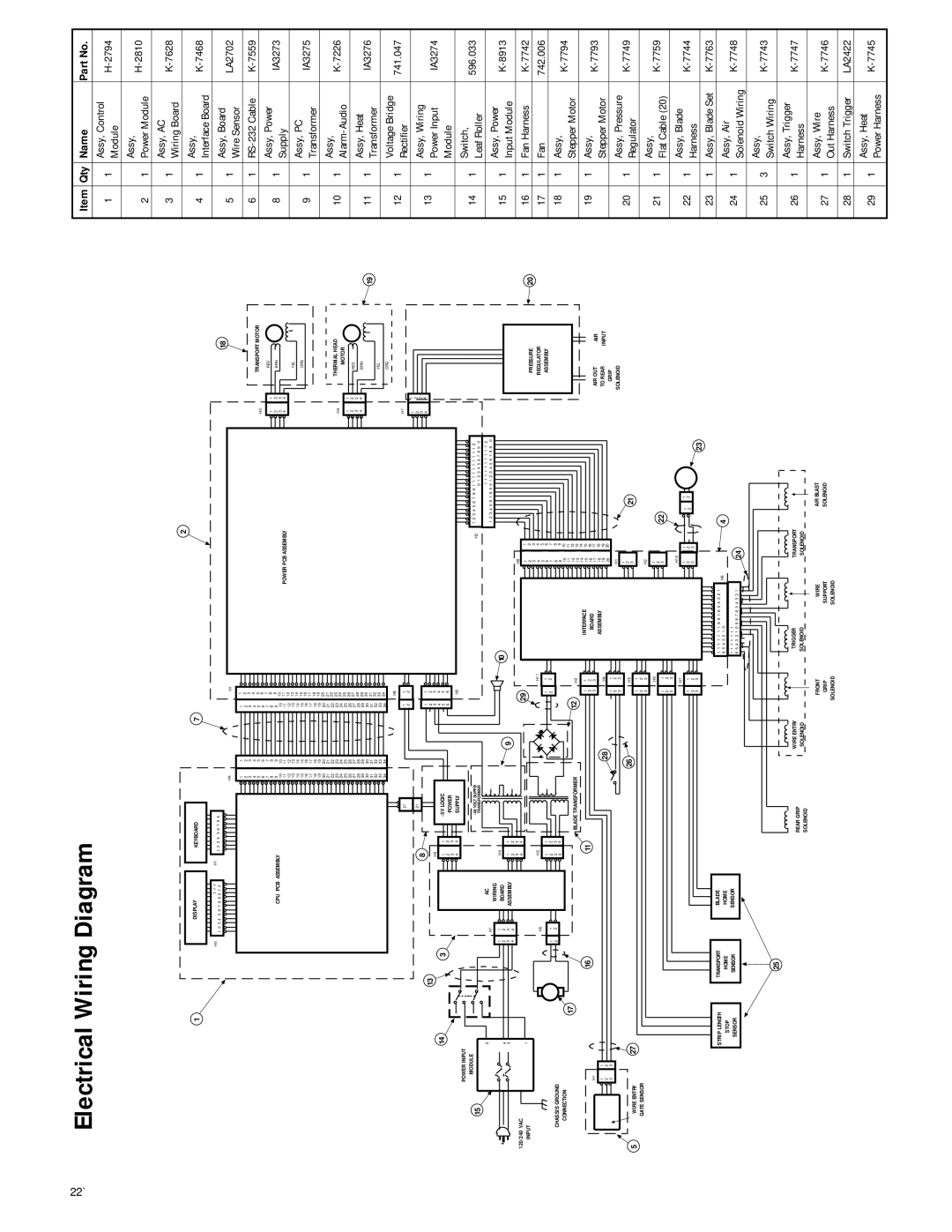
Electrical Wiring Diagram


Item Qty

Name

Part No.

1

1

Assy, Control

H-2794

Module


Assy,

H-2810

2

1

Power Module


3

1

Assy, AC

K-7628

Wiring Board


1

2

4

1

Assy,

K-7468

Interface Board


H1

11

22

33

44

55

66

77

88

99

1010

1111

1212

1313

1414

1515

1616

1717

1818

1919

2020

2121

2222

2323

2424

2525

2626

2727

2828

2929

3030

3131

3232

3333

3434

H6

1

1

2

2

1

1

2

2

3

3

POWER PCB ASSEMBLY

+5V LOGIC POWER SUPPLY


18

H3


TRANSPORT MOTOR


1

1

RED


2

2

BRN

3

3


4

4


YEL


ORG

H4


THERMAL HEAD


MOTOR

1

1


2

2

RED

3

3


4

4

BRN

19

YEL

ORG

H7

11

22

33

44

5

1

Assy, Board

LA2702

Wire Sensor


6

1

RS-232 Cable

K-7559

8

1

Assy, Power

IA3273

Supply


9

1

Assy, PC

IA3275

Transformer


10

1

Assy,

K-7226

Alarm-Audio


11

1

Assy, Heat

IA3276

Transformer


12

1

Voltage Bridge

741.047

Rectifier


13

1

Assy, Wiring


Power Input

IA3274


15

120/240 VAC

INPUT

14

POWER INPUT

MODULE

2

4

3

1

4

4

5

5

6

6

H5

H2

1 2 3 4 5 6 7 8 9 1 1 1 1 1 1 1 1 1 1 2


0 1 2 3 4 5 6 7 8 9

0


1 1 1 1 1 1 1 1 1 1 2

1 2 3 4 5 6 7 8 9 0 1 2 3 4 5 6 7 8 9 0


10


29


H9


1

1


2

2


H11

3

3


4

4

1

1

5

5

6

6

2

2

7

7

PRESSURE

20

REGULATOR


ASSEMBLY


Module


14

1

Switch,

596.033

Leaf Roller


15

1

Assy, Power

K-8913

Input Module


16

1

Fan Harness

K-7742

17

1

Fan

742.006

CHASSIS GROUND

CONNECTION

17

H1

11

22

33

5

WIRE ENTRY

27


GATE SENSOR


STRIP LENGTH

STOP

SENSOR

DISPLAY


KEYBOARD

7

H5

1 1 1

H1

1 2 3 4

5 6 7 8 9


1 2 3 4

5 6 7 8 9 0 1 2


H4


1

1


2

2


3

3


4

4


5

5


6

6


7

7


8

8


CPU PCB ASSEMBLY


9

9


10

10


11

11


12

12


13

13


14

14


15

15


16

16


17

17


18

18


19

19


20

20


21

21


22

22


23

23


24

24


25

25


26

26


27

27


28

28


29

29


30

30


31

31


32

32


33

33


34

34


21


8


21

13


H3


3


1

1

-5V LOGIC


2

2

POWER


3

3


4

4

SUPPLY


-48 VOLT SUPPLY


TRANSFORMER


H1

AC


WIRING


1

1

H4


BOARD


2

2

1

1

9

3

3

ASSEMBLY

4

4

2

2


3

3


4

4


H5

H2

-

+


1

1


1

1

2

2


2

2

3

3


4

4


BLADE TRANSFORMER

16

11

28

26

TRANSPORT


BLADE

HOME


HOME

SENSOR


SENSOR


8

8


9

9


10

10

12


11

11

H3


12

12


13

13

1

1

INTERFACE

14

14

15

15

2

2

BOARD

16

16

3

3

17

17


H4

ASSEMBLY

18

18


19

19

1

1


20

20

2

2


H1


3

3


1


H5


2

21


3


11

22

3

3

H2


H6

1


2


22


1

1

3


2

2


3

3

H10


H7


1

1

1

1

1

1

2

2

2

2

2

2

3

3


23

3

3


1 1 1 1 1 1 1 9 8 7 6 5 4 3 2 1

H8

4

6 5 4 3 2 1 0

1 1 1 1 1 1 1


24

6 5 4 3 2 1 0 9 8 7 6 5 4 3 2 1


AIR OUT

AIR

TO REAR

INPUT

GRIP


SOLENOID


18

1

Assy,

K-7794


Stepper Motor


19

1

Assy,

K-7793


Stepper Motor


20

1

Assy, Pressure

K-7749

Regulator


21

1

Assy,

K-7759

Flat Cable (20)


22

1

Assy, Blade

K-7744

Harness


23

1

Assy, Blade Set

K-7763

24

1

Assy, Air

K-7748

Solenoid Wiring


25

3

Assy,

K-7743

Switch Wiring


25

REAR GRIP

WIRE ENTRY


TRIGGER


TRANSPORT


SOLENOID

SOLENOID


SOLENOID


SOLENOID


FRONT

WIRE

AIR BLAST


GRIP

SUPPORT

SOLENOID


SOLENOID

SOLENOID


26

1

Assy, Trigger

K-7747

Harness


27

1

Assy, Wire

K-7746

Out Harness


28

1

Switch Trigger

LA2422

29

1

Assy, Heat

K-7745

Power Harness


Page 22
Image 22
IDEAL INDUSTRIES 45-930, 45-935 operation manual Electrical Wiring Diagram

45-930, 45-935 specifications

IDEAL Industries is recognized for its commitment to providing high-quality tools and connectors, particularly in the electrical and telecommunications sectors. Among its extensive range of offerings, the IDEAL INDUSTRIES 45-935 and 45-930 stand out as exceptional products tailored to enhance precision and efficiency in various applications.

The IDEAL INDUSTRIES 45-935, commonly known as the Wire Connector Kit, is meticulously engineered to facilitate seamless electrical connectivity. One of its most notable features is its compact design, which allows for easy handling and storage. The kit includes a variety of wire connectors that cater to different gauge sizes, making it an ideal solution for both professional electricians and DIY enthusiasts. This versatile set not only enhances connectivity but also ensures that connections remain secure and reliable over time.

On the other hand, the IDEAL INDUSTRIES 45-930, recognized as the Pro Series Wire Connector, boasts advanced technologies designed for superior performance. Notably, it incorporates an innovative rubber seal that provides moisture resistance, ensuring durable connections in outdoor and damp environments. The connectors are constructed with a high-grade, flame-retardant material, further enhancing their reliability and safety features.

Both products emphasize ease of use. They are designed with color-coded wire connections and ergonomic shapes, allowing for quick identification and hassle-free installation. The intuitive design minimizes the risk of errors during the connection process, significantly reducing installation time and enhancing overall productivity.

Another significant characteristic of the IDEAL INDUSTRIES 45-935 and 45-930 is their compliance with industry standards. They undergo rigorous testing to ensure that they meet or exceed necessary safety guidelines, providing users with peace of mind when utilizing these connectors in their projects.

Furthermore, IDEAL Industries has a strong legacy of innovation. The company continually seeks to improve its products through research and customer feedback, resulting in tools that not only meet current market demands but also anticipate future needs.

In summary, the IDEAL INDUSTRIES 45-935 and 45-930 are exemplary tools that combine superior engineering, user-friendly design, and advanced technologies, making them indispensable assets for anyone in the electrical field. Whether for professional installations or home projects, these products promise reliability, safety, and efficiency in every connection.