GETTING STARTED
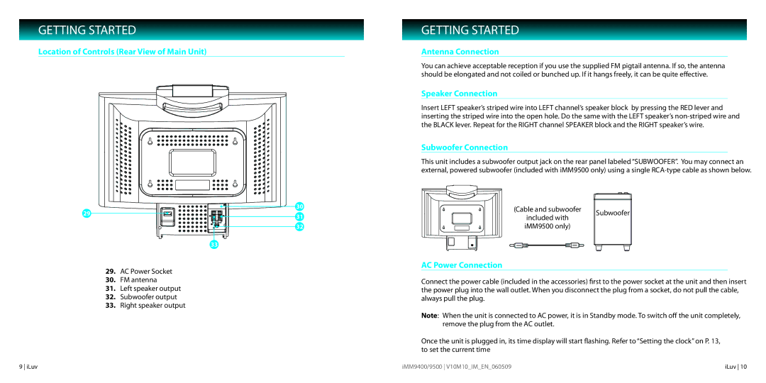
Location of Controls (Rear View of Main Unit)
30
29 | 31 |
| |
| 32 |
| 33 |
29.AC Power Socket
30.FM antenna
31.Left speaker output
32.Subwoofer output
33.Right speaker output
GETTING STARTED
Antenna Connection
You can achieve acceptable reception if you use the supplied FM pigtail antenna. If so, the antenna should be elongated and not coiled or bunched up. If it hangs freely, it can be quite effective.
Speaker Connection
Insert LEFT speaker’s striped wire into LEFT channel’s speaker block by pressing the RED lever and inserting the striped wire into the open hole. Do the same with the LEFT speaker’s
Subwoofer Connection
This unit includes a subwoofer output jack on the rear panel labeled “SUBWOOFER”. You may connect an external, powered subwoofer (included with iMM9500 only) using a single
(Cable and subwoofer | Subwoofer | |
included with | ||
| ||
iMM9500 only) |
|
AC Power Connection
Connect the power cable (included in the accessories) first to the power socket at the unit and then insert the power plug into the wall outlet. When you disconnect the plug from a socket, do not pull the cable, always pull the plug.
Note: When the unit is connected to AC power, it is in Standby mode. To switch off the unit completely, remove the plug from the AC outlet.
Once the unit is plugged in, its time display will start flashing. Refer to “Setting the clock” on P. 13, to set the current time
9 iLuv | iMM9400/9500 V10M10_IM_EN_060509 | iLuv 10 |