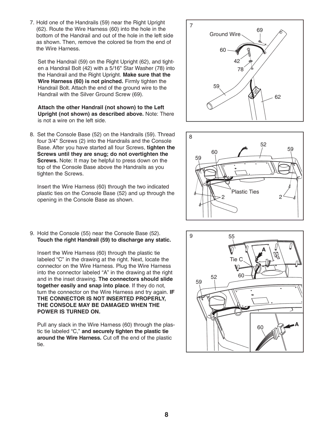
7.Hold one of the Handrails (59) near the Right Upright (62). Route the Wire Harness (60) into the hole in the bottom of the Handrail and out of the hole in the left side as shown. Then, remove the colored tie from the end of the Wire Harness.
Set the Handrail (59) on the Right Upright (62), and tight- en a Handrail Bolt (42) with a 5/16" Star Washer (78) into the Handrail and the Right Upright. Make sure that the Wire Harness (60) is not pinched. Firmly tighten the Handrail Bolt. Attach the end of the ground wire to the Handrail with the Silver Ground Screw (69).
Attach the other Handrail (not shown) to the Left Upright (not shown) as described above. Note: There is not a wire on the left side.
8. Set the Console Base (52) on the Handrails (59). Thread |
four 3/4" Screws (2) into the Handrails and the Console |
Base. After you have started all four Screws, tighten the |
Screws until they are snug; do not overtighten the |
Screws. Note: It may be helpful to press down on the |
top of the Console Base above the Handrails as you |
tighten the Screws. |
Insert the Wire Harness (60) through the two indicated |
plastic ties on the Console Base (52) and up through the |
opening in the Console Base as shown. |
9. Hold the Console (55) near the Console Base (52). |
Touch the right Handrail (59) to discharge any static. |
Insert the Wire Harness (60) through the plastic tie |
7
69
Ground Wire
60 |
|
| 42 |
| 78 |
59 |
|
| 62 |
8 |
|
| 52 |
60 | 59 |
| |
59 |
|
| Plastic Ties |
2 | 2 |
9 | 55 |
| A |
labeled “C” in the drawing at the right. Next, locate the |
connector on the Wire Harness. Plug the Wire Harness |
into the connector labeled “A” in the drawing at the right |
and in the inset drawing. The connectors should slide |
together easily and snap into place. If they do not, |
turn the connector on the Wire Harness and try again. IF |
THE CONNECTOR IS NOT INSERTED PROPERLY, |
THE CONSOLE MAY BE DAMAGED WHEN THE |
POWER IS TURNED ON. |
Pull any slack in the Wire Harness (60) through the plas- |
tic tie labeled “C,” and securely tighten the plastic tie |
around the Wire Harness. Cut off the end of the plastic |
tie. |
Tie C
52 | 60 |
59
60
A
8