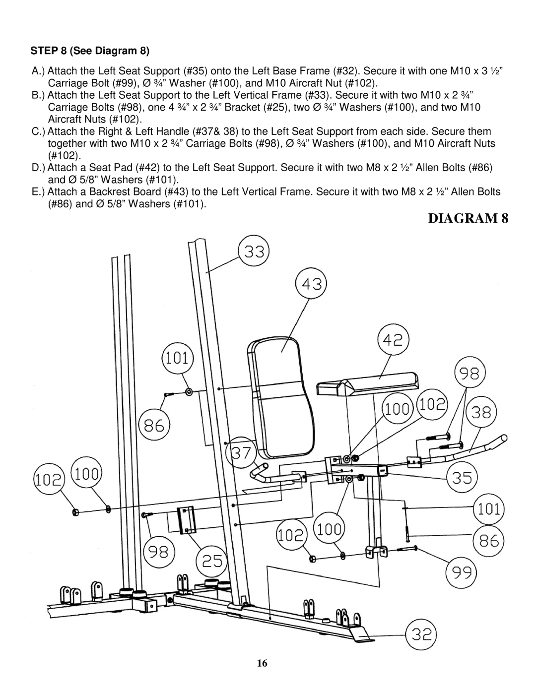
STEP 8 (See Diagram 8)
A.) Attach the Left Seat Support (#35) onto the Left Base Frame (#32). Secure it with one M10 x 3 ½” Carriage Bolt (#99), Ø ¾” Washer (#100), and M10 Aircraft Nut (#102).
B.) Attach the Left Seat Support to the Left Vertical Frame (#33). Secure it with two M10 x 2 ¾” Carriage Bolts (#98), one 4 ¾” x 2 ¾” Bracket (#25), two Ø ¾” Washers (#100), and two M10 Aircraft Nuts (#102).
C.) Attach the Right & Left Handle (#37& 38) to the Left Seat Support from each side. Secure them together with two M10 x 2 ¾” Carriage Bolts (#98), Ø ¾” Washers (#100), and M10 Aircraft Nuts (#102).
D.) Attach a Seat Pad (#42) to the Left Seat Support. Secure it with two M8 x 2 ½” Allen Bolts (#86) and Ø 5/8” Washers (#101).
E.) Attach a Backrest Board (#43) to the Left Vertical Frame. Secure it with two M8 x 2 ½” Allen Bolts (#86) and Ø 5/8” Washers (#101).
DIAGRAM 8
16