300-301 FLOW GUN 1/4 inch SEAT TUNGSTEN CARBIDE
| |||||||
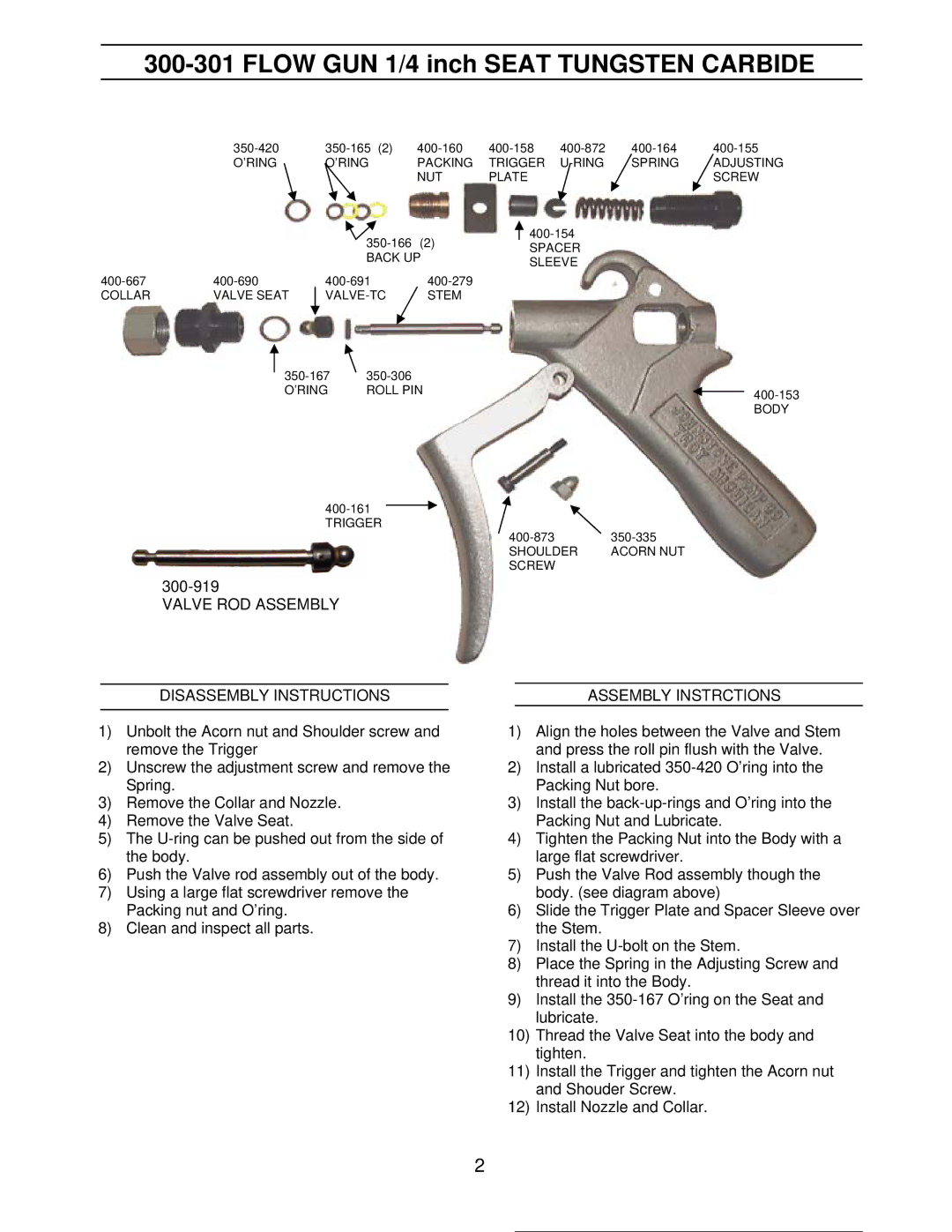
| O’RING | O’RING | PACKING | TRIGGER | SPRING | ADJUSTING | |
|
|
| NUT | PLATE |
|
| SCREW |
|
| (2) |
|
| |||
|
| SPACER |
|
| |||
|
| BACK UP |
|
| |||
|
| SLEEVE |
|
| |||
|
|
|
|
|
| ||
|
|
|
| ||||
COLLAR | VALVE SEAT | STEM |
|
|
|
| |
| ||
O’RING | ROLL PIN | |
|
| BODY |
| |
TRIGGER |
|
SHOULDER | ACORN NUT |
SCREW |
|
VALVE ROD ASSEMBLY
DISASSEMBLY INSTRUCTIONS
1)Unbolt the Acorn nut and Shoulder screw and remove the Trigger
2)Unscrew the adjustment screw and remove the Spring.
3)Remove the Collar and Nozzle.
4)Remove the Valve Seat.
5)The
6)Push the Valve rod assembly out of the body.
7)Using a large flat screwdriver remove the Packing nut and O’ring.
8)Clean and inspect all parts.
ASSEMBLY INSTRCTIONS
1)Align the holes between the Valve and Stem and press the roll pin flush with the Valve.
2)Install a lubricated
3)Install the
4)Tighten the Packing Nut into the Body with a large flat screwdriver.
5)Push the Valve Rod assembly though the body. (see diagram above)
6)Slide the Trigger Plate and Spacer Sleeve over the Stem.
7)Install the
8)Place the Spring in the Adjusting Screw and thread it into the Body.
9)Install the
10)Thread the Valve Seat into the body and tighten.
11)Install the Trigger and tighten the Acorn nut and Shouder Screw.
12)Install Nozzle and Collar.
2