Chateau™ Decorative Gas Appliance
Operating Instructions
Glass Information
Only glass approved by CFM Corporation should be used on this fireplace.
•The use of any
•Care must be taken to avoid breakage of the glass.
•Do not operate appliance with glass front removed, cracked or broken.
•A replacement glass frame assembly (complete with gasket) is available through your CFM Corporation dealer and should only be installed by a licensed qualified service person.
Glass Frame Assembly Removal
1.Turn the fireplace OFF (including the pilot).
2.If the unit has been operating allow time for the components to cool.
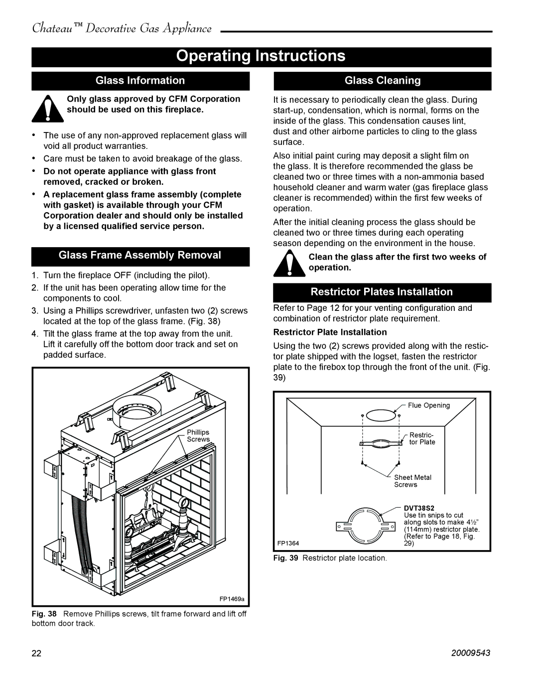
3.Using a Phillips screwdriver, unfasten two (2) screws located at the top of the glass frame. (Fig. 38)
4.Tilt the glass frame at the top away from the unit. Lift it carefully off the bottom door track and set on padded surface.
Phillips |
Screws |
FP1469a
Fig. 38 Remove Phillips screws, tilt frame forward and lift off bottom door track.
Glass Cleaning
It is necessary to periodically clean the glass. During
Also initial paint curing may deposit a slight film on the glass. It is therefore recommended the glass be cleaned two or three times with a
After the initial cleaning process the glass should be cleaned two or three times during each operating season depending on the environment in the house.
Clean the glass after the first two weeks of operation.
Restrictor Plates Installation
Refer to Page 12 for your venting configuration and combination of restrictor plate requirement.
Restrictor Plate Installation
Using the two (2) screws provided along with the restic- tor plate shipped with the logset, fasten the restrictor plate to the firebox top through the front of the unit. (Fig. 39)
| Flue Opening |
| Restric- |
| tor Plate |
| Sheet Metal |
| Screws |
| DVT38S2 |
| Use tin snips to cut |
| along slots to make 4¹⁄₂” |
| (114mm) restrictor plate. |
| (Refer to Page 18, Fig. |
FP1364 | 29) |
Fig. 39 Restrictor plate location.
22 | 20009543 |