PILOT
HONEYWELL IGNITION MODULE
MV | MV/VP PV | 24V | 24V | SENSE SPARK | ||
GRD | ||||||
1 | 2 | 3 | 5 | 6 | 8 | 9 |
RED |
| GREEN | BLACK |
|
| ||
|
|
| |
| ORANGE | ORANGE |
|
|
|
|
| HI |
|
To Receptacle |
|
|
Supplied in |
|
|
Valve Box | NOVA SIT 822 VALVE |
|
| BLUE | |
120 VAC RTN | 24 VAC HOT | BLACK |
|
| |
WHITE | BLACK |
|
|
| WHITE |
BLACK | YELLOW |
|
GREEN |
|
|
120 VAC HOT | 24 VAC RET |
|
| 40VA TRANSFORMER | WALL SWITCH |
|
| |
| BLACK | WHITE |
FP1225
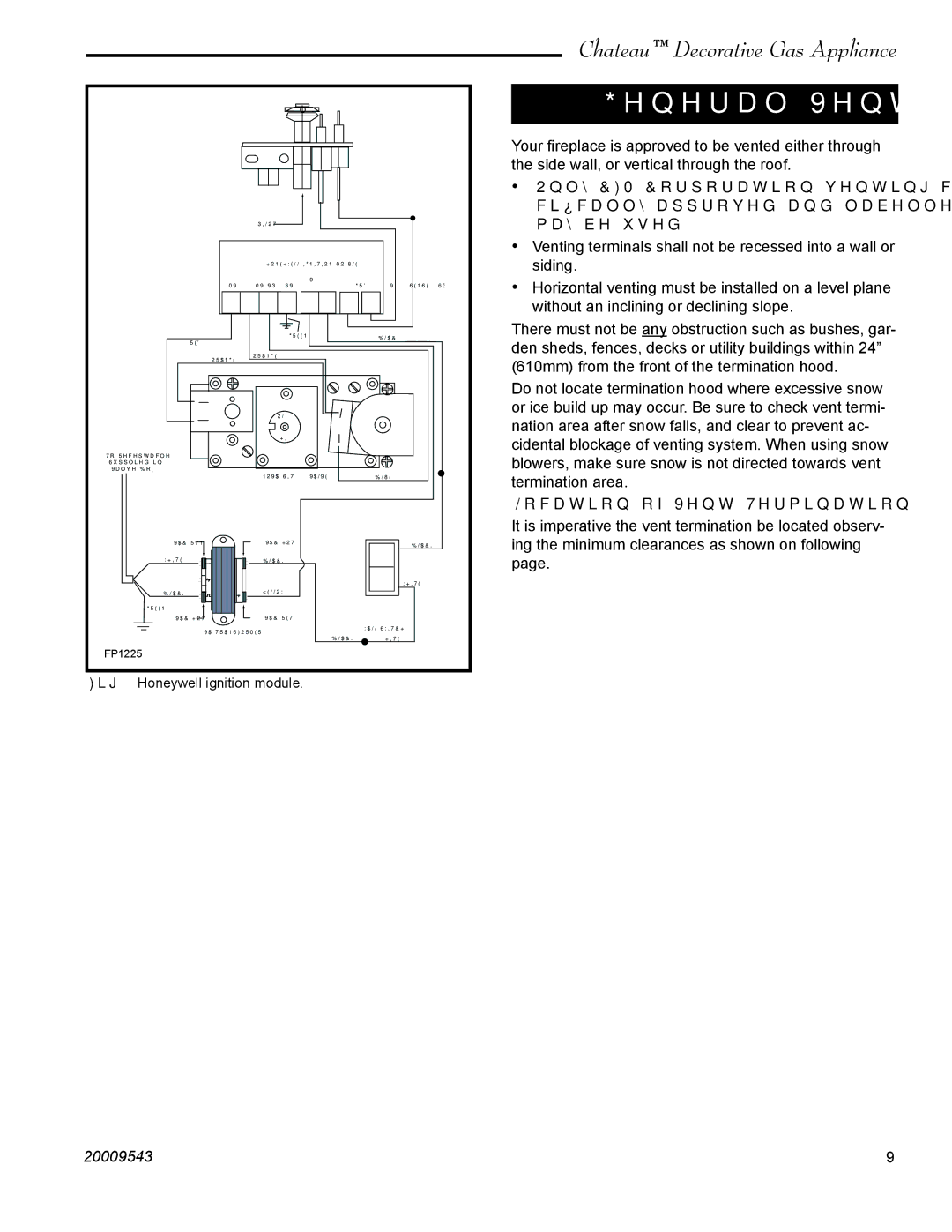
Fig. 10 Honeywell ignition module.
Chateau™ Decorative Gas Appliance
General Venting
Your fireplace is approved to be vented either through the side wall, or vertical through the roof.
•Only CFM Corporation venting components spe- cifically approved and labelled for this fireplace may be used.
•Venting terminals shall not be recessed into a wall or siding.
•Horizontal venting must be installed on a level plane without an inclining or declining slope.
There must not be any obstruction such as bushes, gar- den sheds, fences, decks or utility buildings within 24” (610mm) from the front of the termination hood.
Do not locate termination hood where excessive snow or ice build up may occur. Be sure to check vent termi- nation area after snow falls, and clear to prevent ac- cidental blockage of venting system. When using snow blowers, make sure snow is not directed towards vent termination area.
Location of Vent Termination
It is imperative the vent termination be located observ- ing the minimum clearances as shown on following page.
20009543 | 9 |