Chateau™ Decorative Gas Appliance
Sidewall Installation
STEP 1
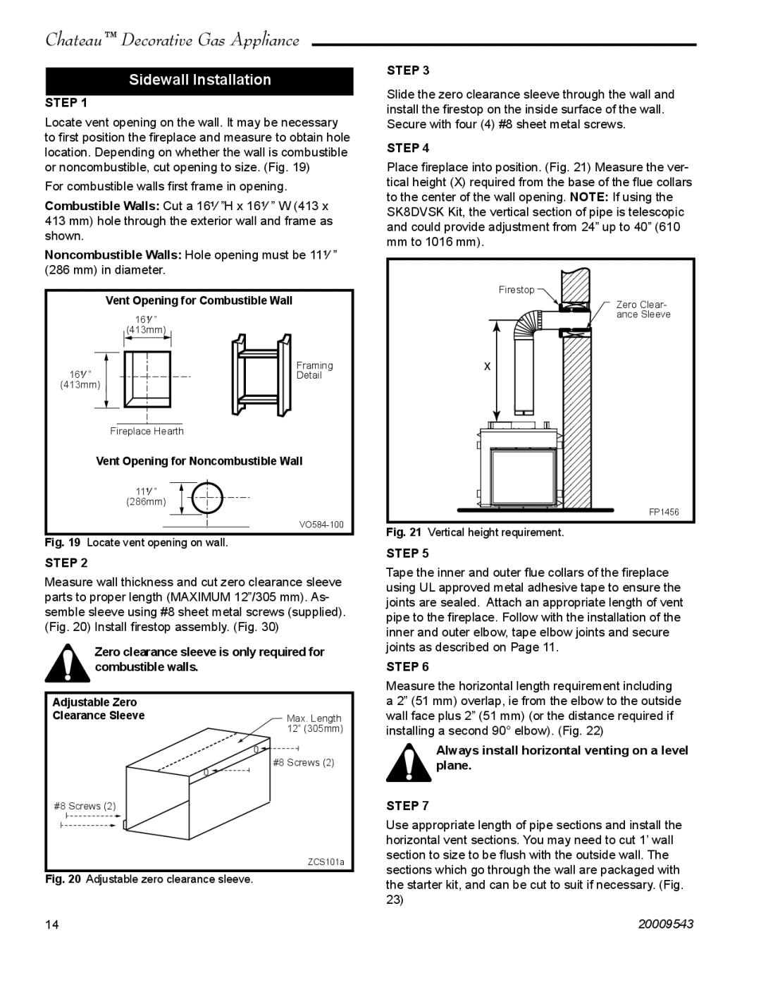
Locate vent opening on the wall. It may be necessary to first position the fireplace and measure to obtain hole location. Depending on whether the wall is combustible or noncombustible, cut opening to size. (Fig. 19)
For combustible walls first frame in opening.
Combustible Walls: Cut a 16¹⁄₄”H x 16¹⁄₄” W (413 x 413 mm) hole through the exterior wall and frame as shown.
Noncombustible Walls: Hole opening must be 11¹⁄₄” (286 mm) in diameter.
Vent Opening for Combustible Wall
16¹⁄₄”
(413mm)
16¹⁄₄” |
|
|
|
|
|
| Framing | |
|
|
|
| Detail | ||||
(413mm) |
|
|
|
|
| |||
|
|
|
|
|
|
|
|
|
|
|
|
|
|
|
|
|
|
|
|
|
|
|
|
|
|
|
Fireplace Hearth
Vent Opening for Noncombustible Wall
11¹⁄₄”
(286mm)
Fig. 19 Locate vent opening on wall.
STEP 2
Measure wall thickness and cut zero clearance sleeve parts to proper length (MAXIMUM 12”/305 mm). As- semble sleeve using #8 sheet metal screws (supplied). (Fig. 20) Install firestop assembly. (Fig. 30)
Zero clearance sleeve is only required for combustible walls.
Adjustable Zero |
|
Clearance Sleeve | Max. Length |
| 12” (305mm) |
| #8 Screws (2) |
#8 Screws (2) |
|
| ZCS101a |
Fig. 20 Adjustable zero clearance sleeve. |
|
14 |
|
STEP 3
Slide the zero clearance sleeve through the wall and install the firestop on the inside surface of the wall. Secure with four (4) #8 sheet metal screws.
STEP 4
Place fireplace into position. (Fig. 21) Measure the ver- tical height (X) required from the base of the flue collars to the center of the wall opening. NOTE: If using the SK8DVSK Kit, the vertical section of pipe is telescopic and could provide adjustment from 24” up to 40” (610 mm to 1016 mm).
Firestop
Zero Clear-
ance Sleeve
X
FP1456
Fig. 21 Vertical height requirement.
STEP 5
Tape the inner and outer flue collars of the fireplace using UL approved metal adhesive tape to ensure the joints are sealed. Attach an appropriate length of vent pipe to the fireplace. Follow with the installation of the inner and outer elbow, tape elbow joints and secure joints as described on Page 11.
STEP 6
Measure the horizontal length requirement including a 2” (51 mm) overlap, ie from the elbow to the outside wall face plus 2” (51 mm) (or the distance required if installing a second 90° elbow). (Fig. 22)
Always install horizontal venting on a level plane.
STEP 7
Use appropriate length of pipe sections and install the horizontal vent sections. You may need to cut 1’ wall section to size to be flush with the outside wall. The sections which go through the wall are packaged with the starter kit, and can be cut to suit if necessary. (Fig. 23)
20009543