������
�������
������
![]() �������FP1362
�������FP1362
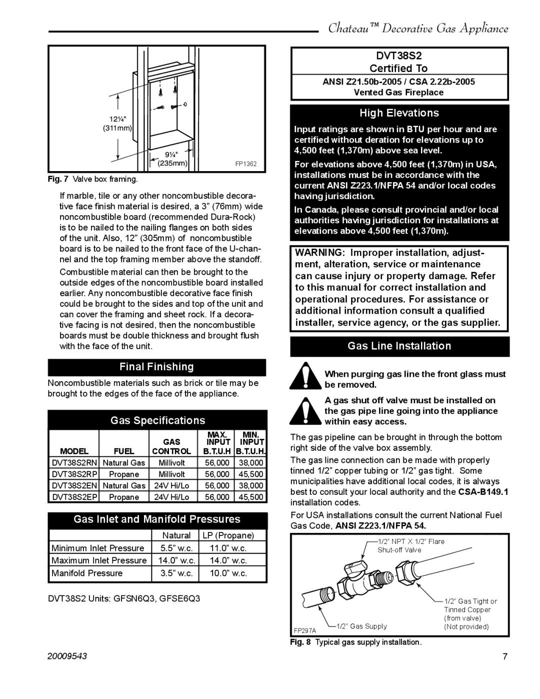
Fig. 7 Valve box framing.
If marble, tile or any other noncombustible decora- tive face finish material is desired, a 3” (76mm) wide noncombustible board (recommended
Combustible material can then be brought to the outside edges of the noncombustible board installed earlier. Any noncombustible decorative face finish could be brought to the sides and top of the unit and can cover the framing and sheet rock. If a decora- tive facing is not desired, then the noncombustible boards must be double thickness and brought flush with the face of the unit.
Final Finishing
Noncombustible materials such as brick or tile may be brought to the edges of the face of the appliance.
Gas Specifications
|
| GAS | MAX. | MIN. |
|
| INPUT | INPUT | |
MODEL | FUEL | CONTROL | B.T.U.H | B.T.U.H. |
DVT38S2RN | Natural Gas | Millivolt | 56,000 | 38,000 |
DVT38S2RP | Propane | Millivolt | 56,000 | 45,500 |
DVT38S2EN | Natural Gas | 24V Hi/Lo | 56,000 | 38,000 |
DVT38S2EP | Propane | 24V Hi/Lo | 56,000 | 45,500 |
Gas Inlet and Manifold Pressures
| Natural | LP (Propane) |
Minimum Inlet Pressure | 5.5” w.c. | 11.0” w.c. |
Maximum Inlet Pressure | 14.0” w.c. | 14.0” w.c. |
Manifold Pressure | 3.5” w.c. | 10.0” w.c. |
|
|
|
DVT38S2 Units: GFSN6Q3, GFSE6Q3
Chateau™ Decorative Gas Appliance
DVT38S2
Certified To
ANSI
Vented Gas Fireplace
High Elevations
Input ratings are shown in BTU per hour and are certified without deration for elevations up to 4,500 feet (1,370m) above sea level.
For elevations above 4,500 feet (1,370m) in USA, installations must be in accordance with the current ANSI Z223.1/NFPA 54 and/or local codes having jurisdiction.
In Canada, please consult provincial and/or local authorities having jurisdiction for installations at elevations above 4,500 feet (1,370m).
WARNING: Improper installation, adjust- ment, alteration, service or maintenance can cause injury or property damage. Refer to this manual for correct installation and operational procedures. For assistance or additional information consult a qualified installer, service agency, or the gas supplier.
Gas Line Installation
When purging gas line the front glass must be removed.
A gas shut off valve must be installed on the gas pipe line going into the appliance within easy access.
The gas pipeline can be brought in through the bottom right side of the valve box assembly.
The gas line connection can be made with properly tinned 1/2” copper tubing or 1/2” gas tight. Some municipalities have additional local codes, it is always best to consult your local authority and the
For USA installations consult the current National Fuel Gas Code, ANSI Z223.1/NFPA 54.
1/2” NPT X 1/2” Flare
|
| 1/2” Gas Tight or |
|
| Tinned Copper |
|
| (from valve) |
FP297A | 1/2” Gas Supply | (Not provided) |
|
|
Fig. 8 Typical gas supply installation.
20009543 | 7 |