DOUBLE HYDRAULIC CHECK ASSEMBLIES 46133-( )
Ml05
40
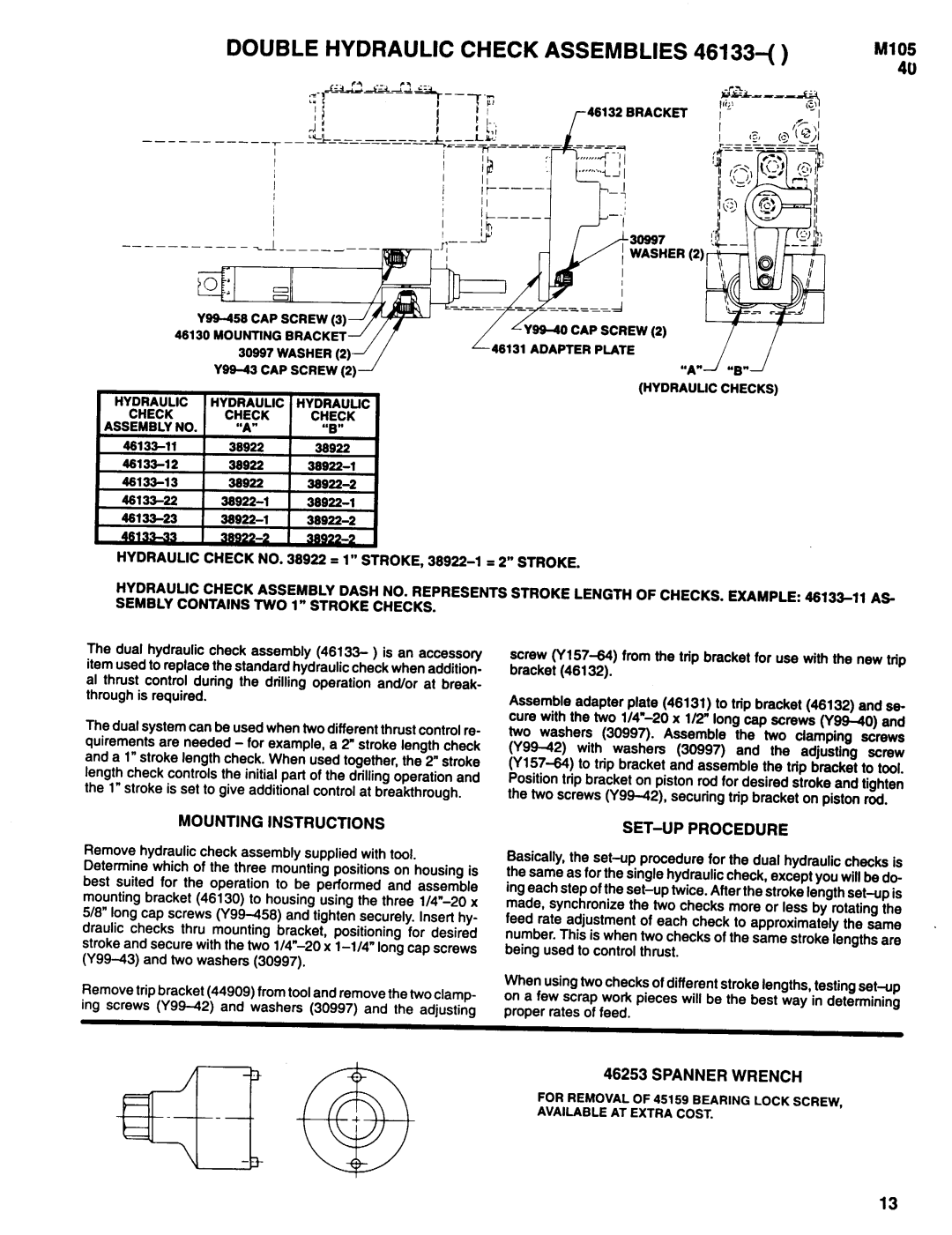
46132 BRACKET
| SCREW (2) |
| |
HYDRAULlC | HYDRAULlC | HYDRAULIC |
|
CHECK | CHECK | CHECK "B" |
|
ASSEMBLY NO. | "A" |
| |
|
| ||
38922 | 38922 |
| |
38922 |
| ||
30922 |
| ||
| |||
| |||
| I |
HYDRAULIC CHECK NO. 38922 = 1”
The dual hydraulic check assembly (46133- ) is an accessory item used to replace the standard hydraulic check when addition- al thrust control during the drilling operation and/or at break- through is required.
The dual system can be used when two different thrust control re- quirements are needed - for example, a 2” stroke length check and a 1” stroke length check. When used together, the 2” stroke length check controls the initial part of the drilling operation and the 1” stroke is set to give additional control at breakthrough.
screw
Assemble adapter plate (48131) to trip bracket (46132) and se- cure with the two 1/4”- 20 x 1/2” long cap screws
MOUNTING INSTRUCTIONS
Remove hydraulic check assembly supplied with tool. Determine which of the three mounting positions on housing is best suited for the operation to be performed and assemble mounting bracket (46130) to housing using the three 1/4”- 20 x 5/8” long cap screws
Remove trip bracket (44909) from tool and remove the two clamp- ing screws
SET-UP PROCEDURE
Basically, the
feed rate adjustment of each check to approximately the same . number. This is when two checks of the same stroke lengths are being used to control thrust.
When using two checks of different stroke lengths, testing
46253 SPANNER WRENCH
FOR REMOVAL OF 45159 BEARING LOCK SCREW, AVAILABLE AT EXTRA COST.
13