Step 2 Setting the Counter-balance
Use the 1/4” allen wrench (provided), insert into the hole on the top of the endcap with shaft; with one hand, hold the arm in a horizontal position, while turning the allen wrench with the other hand to set the weight adjustment. See Illustration 5 below.
Using the allen wrench in a horizontal position allows extra leverage while adjusting.
To increase the weight for heavier monitors, turn the wrench left
1/4” Allen Wrench
Horizontal Position
Endcap
Mount ![]()
To decrease the resistance for lighter monitors, turn the wrench to the right (clockwise).
Illustration 5
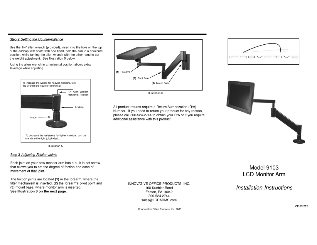
Step 3 Adjusting Friction Joints
Each joint on your new monitor arm has a built in set screw that allows you to set the degree of friction and ease of movement of that joint.
The friction joints are located (1) in the forearm, where the tilter mechanism is inserted, (2) the forearm’s pivot point and
(3)mount base, where monitor arm is inserted.
See Illustration 6 on the next page.
(1)Forearm![]()
(2)Pivot Point
(3)Mount Base
Illustration 6
All product returns require a Return Authorization (R/A) Number. If you need to return your product for any reason, please call
INNOVATIVE OFFICE PRODUCTS, INC.
100 Kuebler Road
Easton, PA 18042
sales@LCDARMS.com
© Innovative Office Products, Inc. 2003
Model 9103
LCD Monitor Arm
Installation Instructions