QUILL ADJUSTMENTS
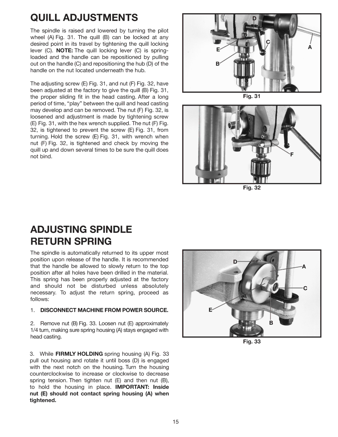
The spindle is raised and lowered by turning the pilot wheel (A) Fig. 31. The quill (B) can be locked at any desired point in its travel by tightening the quill locking lever (C). NOTE: The quill locking lever (C) is spring- loaded and the handle can be repositioned by pulling out on the handle (C) and repositioning the hub (D) of the handle on the nut located underneath the hub.
The adjusting screw (E) Fig. 31, and nut (F) Fig. 32, have been adjusted at the factory to give the quill (B) Fig. 31, the proper sliding fit in the head casting. After a long period of time, “play” between the quill and head casting may develop and can be removed. The nut (F) Fig. 32, is loosened and adjustment is made by tightening screw
(E)Fig. 31, with the hex wrench supplied. The nut (F) Fig. 32, is tightened to prevent the screw (E) Fig. 31, from turning. Hold the screw (E) Fig. 31, with wrench when nut (F) Fig. 32, is tightened and check by moving the quill up and down several times to be sure the quill does not bind.
ADJUSTING SPINDLE
RETURN SPRING
The spindle is automatically returned to its upper most position upon release of the handle. It is recommended that the handle be allowed to slowly return to the top position after all holes have been drilled in the material. This spring has been properly adjusted at the factory and should not be disturbed unless absolutely necessary. To adjust the return spring, proceed as follows:
1.DISCONNECT MACHINE FROM POWER SOURCE.
2.Remove nut (B) Fig. 33. Loosen nut (E) approximately 1/4 turn, making sure spring housing (A) stays engaged with head casting.
3.While FIRMLY HOLDING spring housing (A) Fig. 33 pull out housing and rotate it until boss (D) is engaged with the next notch on the housing. Turn the housing counterclockwise to increase or clockwise to decrease spring tension. Then tighten nut (E) and then nut (B), to hold the housing in place. IMPORTANT: Inside nut (E) should not contact spring housing (A) when tightened.
| D |
| C |
E | A |
| |
B |
|
Fig. 31
F
Fig. 32
D
![]() A
A
C
E
B
Fig. 33
15