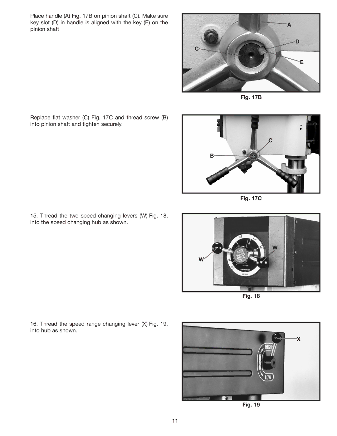
Place handle (A) Fig. 17B on pinion shaft (C). Make sure key slot (D) in handle is aligned with the key (E) on the pinion shaft
Replace flat washer (C) Fig. 17C and thread screw (B) into pinion shaft and tighten securely.
15.Thread the two speed changing levers (W) Fig. 18, into the speed changing hub as shown.
16.Thread the speed range changing lever (X) Fig. 19, into hub as shown.
![]() A
A
D
C![]()
E
Fig. 17B
C
B![]()
Fig. 17C
W
W
Fig. 18
X
Fig. 19
11