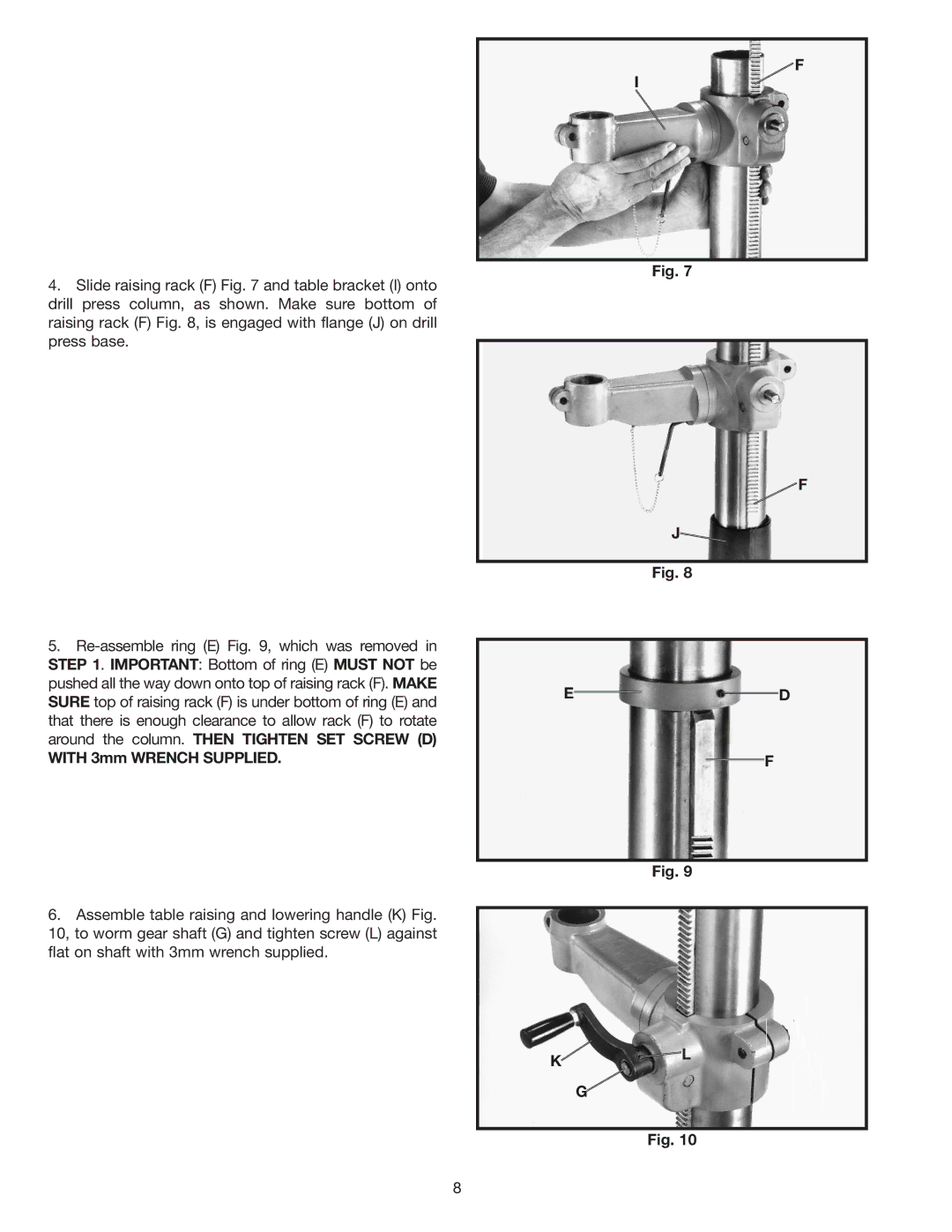
4.Slide raising rack (F) Fig. 7 and table bracket (I) onto drill press column, as shown. Make sure bottom of raising rack (F) Fig. 8, is engaged with flange (J) on drill press base.
5.
WITH 3mm WRENCH SUPPLIED.
6.Assemble table raising and lowering handle (K) Fig. 10, to worm gear shaft (G) and tighten screw (L) against flat on shaft with 3mm wrench supplied.
F
I
Fig. 7
![]() F
F
J![]()
Fig. 8
ED
F
Fig. 9
K![]()
![]() L
L
G![]()
Fig. 10
8