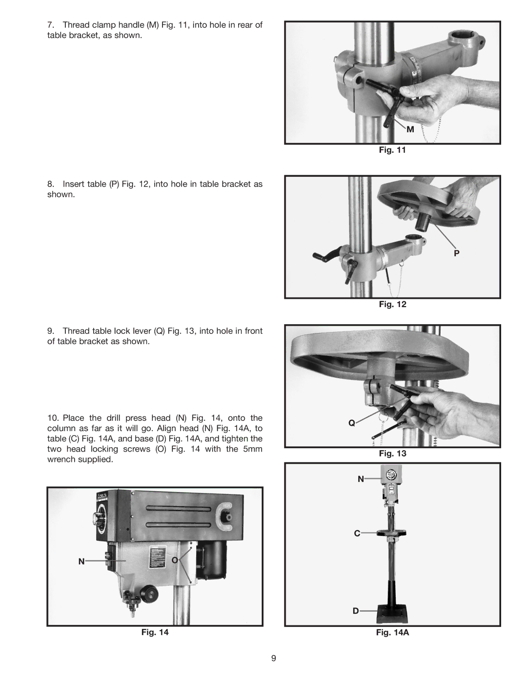
7.Thread clamp handle (M) Fig. 11, into hole in rear of table bracket, as shown.
8.Insert table (P) Fig. 12, into hole in table bracket as shown.
9.Thread table lock lever (Q) Fig. 13, into hole in front of table bracket as shown.
10.Place the drill press head (N) Fig. 14, onto the column as far as it will go. Align head (N) Fig. 14A, to table (C) Fig. 14A, and base (D) Fig. 14A, and tighten the two head locking screws (O) Fig. 14 with the 5mm wrench supplied.
NO![]()
Fig. 14
M
Fig. 11
P
Fig. 12
Q
Fig. 13
N
C
D
Fig. 14A
9