Control Position and Names
Rear Panel
For operational instructions, see the page indicated in brackets [ ].
AC INLET
VIDEO OUTPUT
COMPONENT
PR
VIDEO
PB
RS 232
Y
S VIDEO
|
|
| DIGITAL OUTPUT |
|
|
| AUDIO |
| DVD CHANGER | ||
OUTPUT |
| MODEL NO. | |||
|
|
| COAXIAL OPTICAL |
|
|
L
R
1 2 3 4 5 6 7
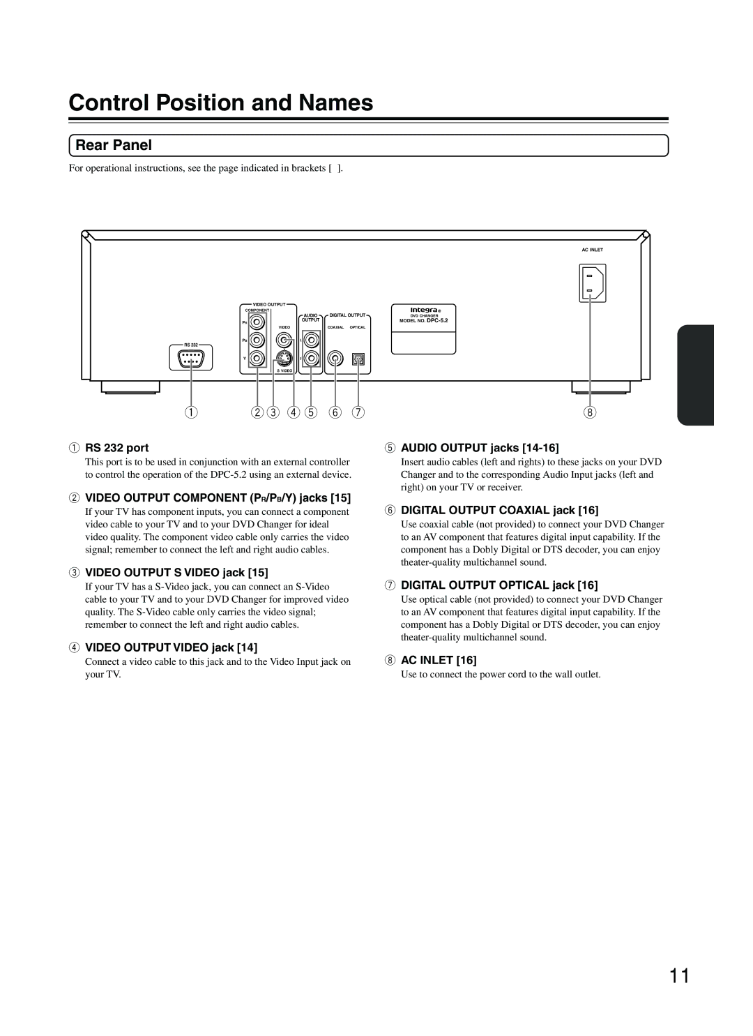
1RS 232 port
This port is to be used in conjunction with an external controller to control the operation of the
2VIDEO OUTPUT COMPONENT (PR/PB/Y) jacks [15]
If your TV has component inputs, you can connect a component video cable to your TV and to your DVD Changer for ideal video quality. The component video cable only carries the video signal; remember to connect the left and right audio cables.
3VIDEO OUTPUT S VIDEO jack [15]
If your TV has a
4VIDEO OUTPUT VIDEO jack [14]
Connect a video cable to this jack and to the Video Input jack on your TV.
8
5AUDIO OUTPUT jacks [14-16]
Insert audio cables (left and rights) to these jacks on your DVD Changer and to the corresponding Audio Input jacks (left and right) on your TV or receiver.
6DIGITAL OUTPUT COAXIAL jack [16]
Use coaxial cable (not provided) to connect your DVD Changer to an AV component that features digital input capability. If the component has a Dobly Digital or DTS decoder, you can enjoy
7DIGITAL OUTPUT OPTICAL jack [16]
Use optical cable (not provided) to connect your DVD Changer to an AV component that features digital input capability. If the component has a Dobly Digital or DTS decoder, you can enjoy
8AC INLET [16]
Use to connect the power cord to the wall outlet.
11
