Integra DTA-9.4 Rear panel facilities and connections, + OUTPUT - Speaker output and binding post

Models: DTA-9.4

1 16
Download 16 pages 43.89 Kb
Page 10
Image 10
Rear panel facilities and connections

Rear panel facilities and connections

+ OUTPUT – (Speaker output and binding post)

The DTA-9.4 is equipped with high-current binding posts for use at output terminals to the speaker system. To obtain the best in sound quality from the DTA-9.4, we recommend the use of high-quality speaker cables.

For each channel, connect the negative (white) output post to the negative input terminal of the speaker and the positive (red) output post to the positive input terminal of the speaker.

12V TRIGGER IN (CONTROL LINK IN)

Connects to the 12V trigger output terminal on the other device to control the DTA-9.4.

Connecting to the Integra DTC-9.4 AV controller:

Use the attached stereo mini-plug cable to connect to the 12V TRIGGER OUT terminal on the DTC-9.4.

Connecting to the 12V TRIGGER OUT B (CONTROL LINK OUT) terminal:

This enables the DTA-9.4 to turn on or go into standby state based on the power on/standby status of the DTC-9.4. The brightness of the On or Standby indicator on the DTA-9.4 also switches automatically in 4 levels according to the dimmer setting (brightness adjustment of the display) of the DTC-9.4.

Connecting to the 12V TRIGGER OUT A terminal:

This enables the DTA-9.4 to turn on or go into standby state based on the power on/standby status of the DTC-9.4.

Note:

Be sure to use the attached stereo mini-plug cable for connecting to the DTC-9.4. Using any other cables does not allow control of the DTA-9.4 with the Dimmer function to work.

Connecting to any other devices than the DTC-9.4:

Use the commercial 1/8-inch mono cable to connect to the 12V trigger output terminal on the other device. This enables the DTA-

9.4to turn on or go into standby state based on the power on/standby status of other devices.

The tip polarity of the connectors are as shown below.
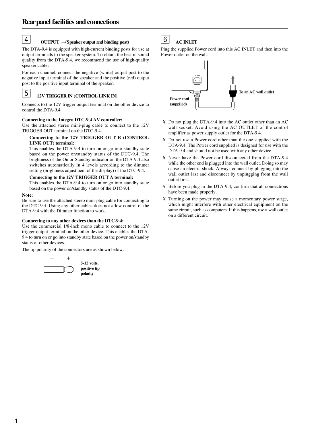
5-12 volts, positive tip polarity

AC INLET

Plug the supplied Power cord into this AC INLET and then into the Power outlet on the wall.

To an AC wall outlet

Power cord (supplied)

Do not plug the DTA-9.4 into the AC outlet other than an AC wall socket. Avoid using the AC OUTLET of the control amplifier as power supply outlet for the DTA-9.4.

Do not use a Power cord other than the one supplied with the DTA-9.4. The Power cord supplied is designed for use with the DTA-9.4 and should not be used with any other device.

Never have the Power cord disconnected from the DTA-9.4 while the other end is plugged into the wall outlet. Doing so may cause an electric shock. Always connect by plugging into the wall outlet last and disconnect by unplugging from the wall outlet first.

Before you plug in the DTA-9.4, confirm that all connections have been made properly.

Turning on the power may cause a momentary power surge, which might interfere with other electrical equipment on the same circuit, such as computers. If this happens, use a wall outlet on a different circuit.

10

Page 10
Image 10
Integra DTA-9.4 Rear panel facilities and connections, + OUTPUT - Speaker output and binding post, Ac Inlet