Connecting to the Integra AV Controller DTC-9.4
Since many users will purchase the
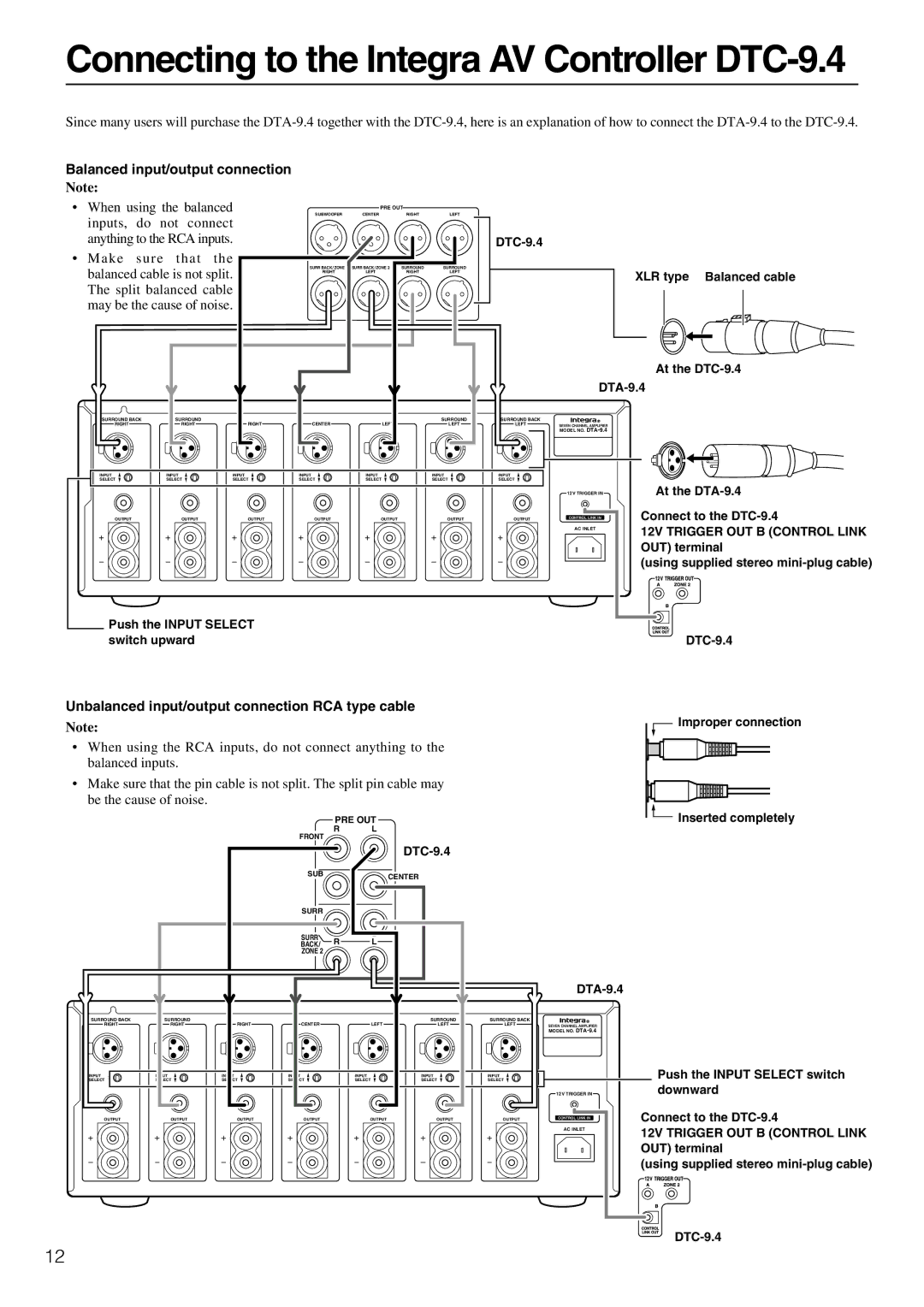
Balanced input/output connection
Note:
•When using the balanced inputs, do not connect anything to the RCA inputs.
•Make sure that the balanced cable is not split. The split balanced cable may be the cause of noise.
PRE OUT
SUBWOOFER | CENTER | RIGHT | LEFT |
SURR BACK / ZONE 2 | SURR BACK / ZONE 2 | SURROUND | SURROUND |
RIGHT | LEFT | RIGHT | LEFT |
DTC-9.4
XLR type Balanced cable
At the DTC-9.4
DTA-9.4
SURROUND BACK | SURROUND |
|
|
| SURROUND |
RIGHT | RIGHT | RIGHT | CENTER | LEFT | LEFT |
SURROUND BACK
LEFT | SEVEN CHANNEL AMPLIFIER |
MODEL NO.
INPUT | INPUT | INPUT | INPUT | INPUT | INPUT | INPUT |
SELECT | SELECT | SELECT | SELECT | SELECT | SELECT | SELECT |
OUTPUT | OUTPUT | OUTPUT | OUTPUT | OUTPUT | OUTPUT | OUTPUT |
![]() Push the INPUT SELECT switch upward
Push the INPUT SELECT switch upward
12V TRIGGER IN
CONTROL LINK IN |
AC INLET |
At the
Connect to the
12V TRIGGER OUT B (CONTROL LINK OUT) terminal
(using supplied stereo
Unbalanced input/output connection RCA type cable
Note:
•When using the RCA inputs, do not connect anything to the balanced inputs.
•Make sure that the pin cable is not split. The split pin cable may be the cause of noise.
|
|
|
| PRE OUT |
|
| |
|
|
| FRONT | R | L |
|
|
|
|
|
|
|
|
| |
|
|
|
|
|
|
| |
|
|
| SUB |
|
| CENTER |
|
|
|
|
|
|
|
| |
|
|
| SURR |
|
|
|
|
|
|
| SURR | R | L |
|
|
|
|
| BACK/ |
|
| ||
|
|
| ZONE 2 |
|
|
|
|
SURROUND BACK | SURROUND |
|
|
|
| SURROUND | SURROUND BACK |
RIGHT | RIGHT | RIGHT | CENTER |
| LEFT | LEFT | LEFT |
Improper connection
Inserted completely
DTA-9.4
INPUT | INPUT | INPUT | INPUT | INPUT | INPUT | INPUT |
SELECT | SELECT | SELECT | SELECT | SELECT | SELECT | SELECT |
OUTPUT | OUTPUT | OUTPUT | OUTPUT | OUTPUT | OUTPUT | OUTPUT |
SEVEN CHANNEL AMPLIFIER
MODEL NO.
12V TRIGGER IN
CONTROL LINK IN |
AC INLET |
Push the INPUT SELECT switch downward
Connect to the
12V TRIGGER OUT B (CONTROL LINK OUT) terminal
(using supplied stereo
12