Integra ST2 SETUP AND CONNECTIONS, BASIC CONNECTIONS ST2-KP RJ-45Connection Wiring, Power

Models: ST2

1 28
Download 28 pages 32.77 Kb
Page 9
Image 9
ST2 SETUP AND CONNECTIONS

ST2 SETUP AND CONNECTIONS

Power

To power the tuner, connect the 12VDC external power supply by inserting the power supply jack into the power supply connection on the tuner’s rear panel.

Audio Output

Connect one end of a dual RCA audio cable to the Tuner 1 Audio Output connection. Keep prop- er channel identity. Attach the other end of the RCA cables to the source input of the audio con- trol system. Repeat the same procedure for the Tuner 2 Audio Output.

BASIC CONNECTIONS

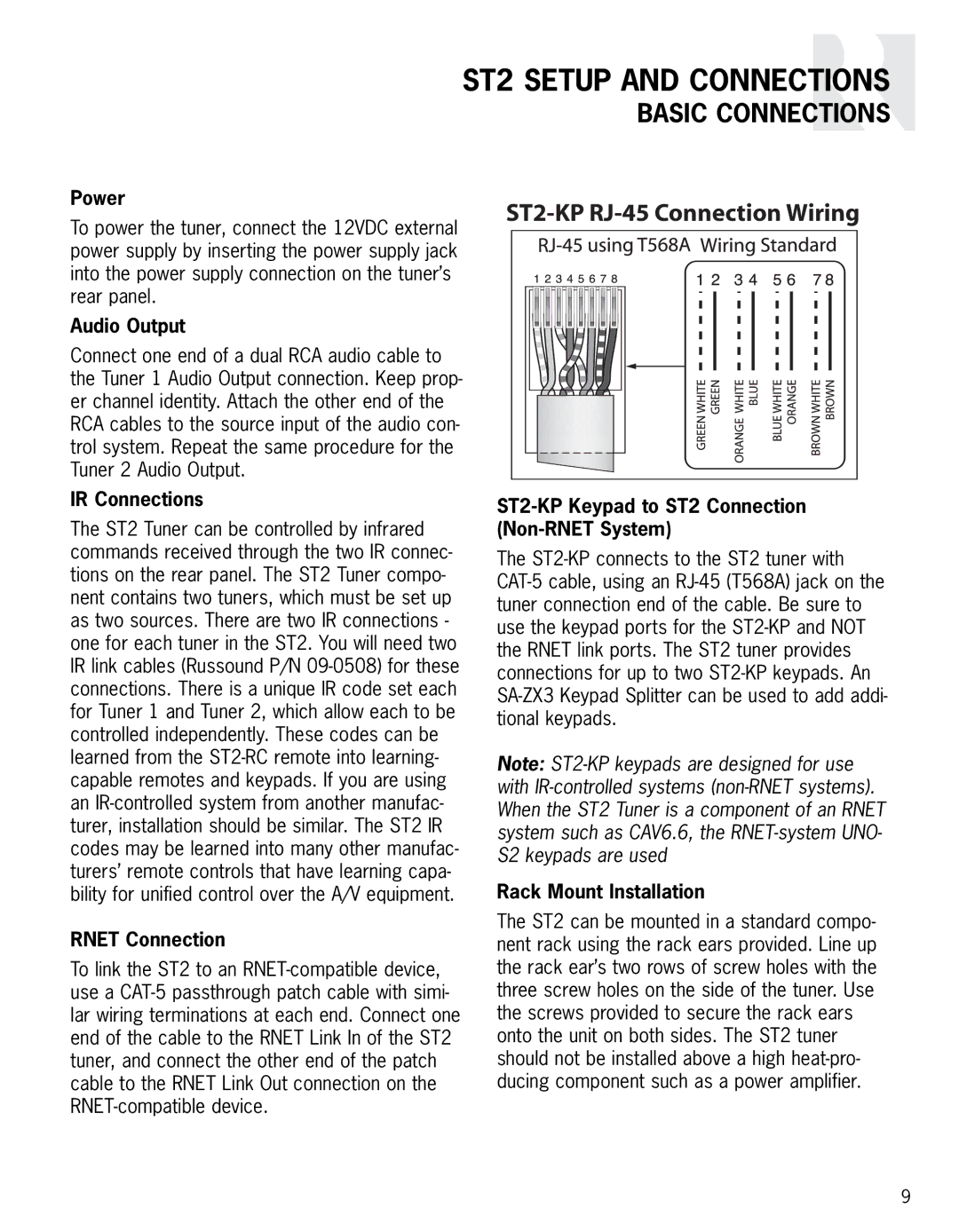
ST2-KP RJ-45 Connection Wiring

IR Connections

The ST2 Tuner can be controlled by infrared commands received through the two IR connec- tions on the rear panel. The ST2 Tuner compo- nent contains two tuners, which must be set up as two sources. There are two IR connections - one for each tuner in the ST2. You will need two IR link cables (Russound P/N 09-0508) for these connections. There is a unique IR code set each for Tuner 1 and Tuner 2, which allow each to be controlled independently. These codes can be learned from the ST2-RC remote into learning- capable remotes and keypads. If you are using an IR-controlled system from another manufac- turer, installation should be similar. The ST2 IR codes may be learned into many other manufac- turers’ remote controls that have learning capa- bility for unified control over the A/V equipment.

RNET Connection

To link the ST2 to an RNET-compatible device, use a CAT-5 passthrough patch cable with simi- lar wiring terminations at each end. Connect one end of the cable to the RNET Link In of the ST2 tuner, and connect the other end of the patch cable to the RNET Link Out connection on the RNET-compatible device.

ST2-KP Keypad to ST2 Connection (Non-RNET System)

The ST2-KP connects to the ST2 tuner with CAT-5 cable, using an RJ-45 (T568A) jack on the tuner connection end of the cable. Be sure to use the keypad ports for the ST2-KP and NOT the RNET link ports. The ST2 tuner provides connections for up to two ST2-KP keypads. An SA-ZX3 Keypad Splitter can be used to add addi- tional keypads.

Note: ST2-KP keypads are designed for use with IR-controlled systems (non-RNET systems). When the ST2 Tuner is a component of an RNET system such as CAV6.6, the RNET-system UNO- S2 keypads are used

Rack Mount Installation

The ST2 can be mounted in a standard compo- nent rack using the rack ears provided. Line up the rack ear’s two rows of screw holes with the three screw holes on the side of the tuner. Use the screws provided to secure the rack ears onto the unit on both sides. The ST2 tuner should not be installed above a high heat-pro- ducing component such as a power amplifier.

9

Page 9
Image 9
Integra ST2 SETUP AND CONNECTIONS, BASIC CONNECTIONS ST2-KP RJ-45Connection Wiring, Power, Audio Output, IR Connections