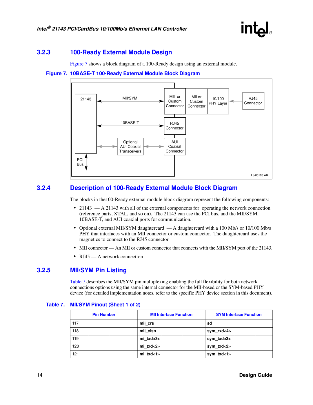
21143 specifications
The Intel 21143 is a widely recognized Ethernet controller that has played a significant role in the development of networking technology throughout the late 1990s and early 2000s. This controller, part of Intel's line of networking solutions, was designed primarily for desktop and server systems, catering to the needs of both home and enterprise-level networking.One of the main features of the Intel 21143 is its support for the IEEE 802.3 standard, allowing it to facilitate Ethernet networking at speeds of up to 100 Mbps. The 21143 supports both the 10Base-T and 100Base-TX Ethernet standards, making it versatile for different network environments. Its ability to auto-negotiate between these speeds ensures compatibility with a wide range of network devices, enhancing its utility in mixed-speed networks.
The Intel 21143 employs an advanced shared memory architecture that enables efficient data transfer and reduces CPU overhead. This feature ensures that the controller can handle higher throughput while allowing the CPU to focus on other tasks. Additionally, the controller supports a direct memory access (DMA) transmission capability, providing further enhancements in data handling and overall system performance.
An important characteristic of the Intel 21143 is its onboard processor, which allows it to offload certain networking tasks from the host CPU. This results in improved overall system performance, as the main processor is freed from handling all network traffic. The controller supports Full Duplex operation, enabling simultaneous sending and receiving of data, effectively doubling the potential bandwidth for each connection.
Another notable technology integrated into the Intel 21143 is its built-in support for TCP/IP checksum calculations. By offloading this computationally intensive task from the CPU, the controller enhances network performance, particularly in data-intensive applications such as file transfers and video streaming.
The Intel 21143 was primarily used in PCI (Peripheral Component Interconnect) applications, which facilitated ease of integration into existing systems. Its compatibility with various operating systems, including Windows and Linux, made it a popular choice among developers and users alike.
Overall, the Intel 21143 Ethernet controller has been instrumental in evolving networking technology. Its impressive features, efficient architecture, and robust performance have solidified its position in the market, paving the way for future advancements in Ethernet networking. Even today, the principles and technologies introduced with the Intel 21143 continue to influence modern networking solutions.

