Intel Desktop Board D945GCLF Product Guide
Connecting to the Front Panel Header
Before connecting to the front panel header, observe the precautions in "Before You Begin" on page 21. See Figure 11, C on page 30 for the location of the front panel header.
Table 6 shows the pin assignments for the front panel header.
Table 6. Front Panel Header Signal Names
Pin | Signal |
| In/Out | Description |
|
|
|
| |
| Hard Drive Activity LED | |||
|
|
|
|
|
1 | HD_PWR |
| Out | Hard disk LED pull- |
| up (330 Ω) to +5 V | |||
|
|
|
| |
|
|
|
|
|
3 | HDA# |
| Out | Hard disk active |
| LED | |||
|
|
|
| |
|
|
|
|
|
|
| Reset Switch | ||
|
|
|
|
|
Pin |
| Signal |
|
| In/Out |
| Description |
|
|
|
|
|
|
|
|
|
|
| Power LED |
|
| ||
2 |
| HDR_BLNK_GRN |
| Out |
| Front panel | |
|
|
| |||||
|
|
| green LED | ||||
|
|
|
|
|
|
| |
4 |
| HDR_BLNK_YEL |
| Out |
| Front panel | |
|
|
| yellow LED | ||||
|
|
|
|
|
|
| |
|
|
|
|
|
|
|
|
|
|
| On/Off Switch |
|
| ||
5 | Ground |
| Ground |
7 | FP_RESET# | In | Reset switch |
|
| Power |
|
|
|
| |
|
|
| |
9 | +5 V |
| Power |
|
|
|
|
6 | SWITCH_ON# | In | Power switch |
|
|
|
|
8 | Ground |
| Ground |
|
|
|
|
| Not Connected |
| |
|
|
|
|
10 | N/C |
| No pin |
|
|
|
|
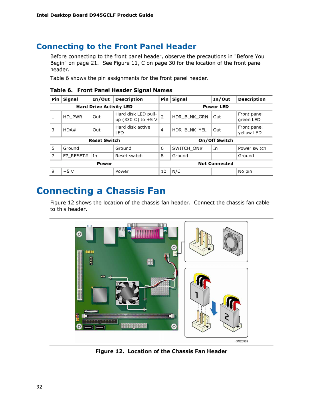
Connecting a Chassis Fan
Figure 12 shows the location of the chassis fan header. Connect the chassis fan cable to this header.
Figure 12. Location of the Chassis Fan Header
32