Technical Reference
2.2.2.7Front Panel USB Headers
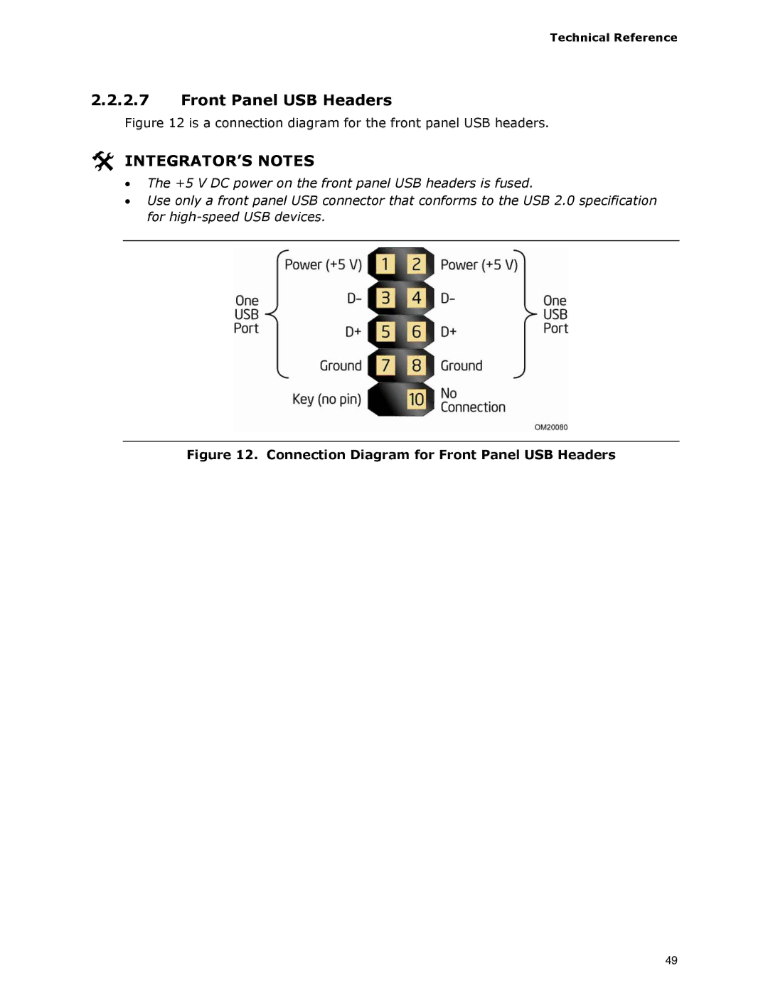
Figure 12 is a connection diagram for the front panel USB headers.
INTEGRATOR’S NOTES
•The +5 V DC power on the front panel USB headers is fused.
•Use only a front panel USB connector that conforms to the USB 2.0 specification for
Figure 12. Connection Diagram for Front Panel USB Headers
49