Intel Desktop Board DG33BU Technical Product Specification
2.2.2Component-side Connectors and Headers
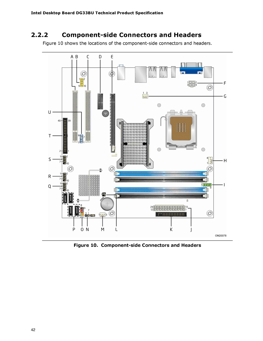
Figure 10 shows the locations of the component-side connectors and headers.
Figure 10. Component-side Connectors and Headers
42