Technical Reference
2.2.2.5Front Panel Header
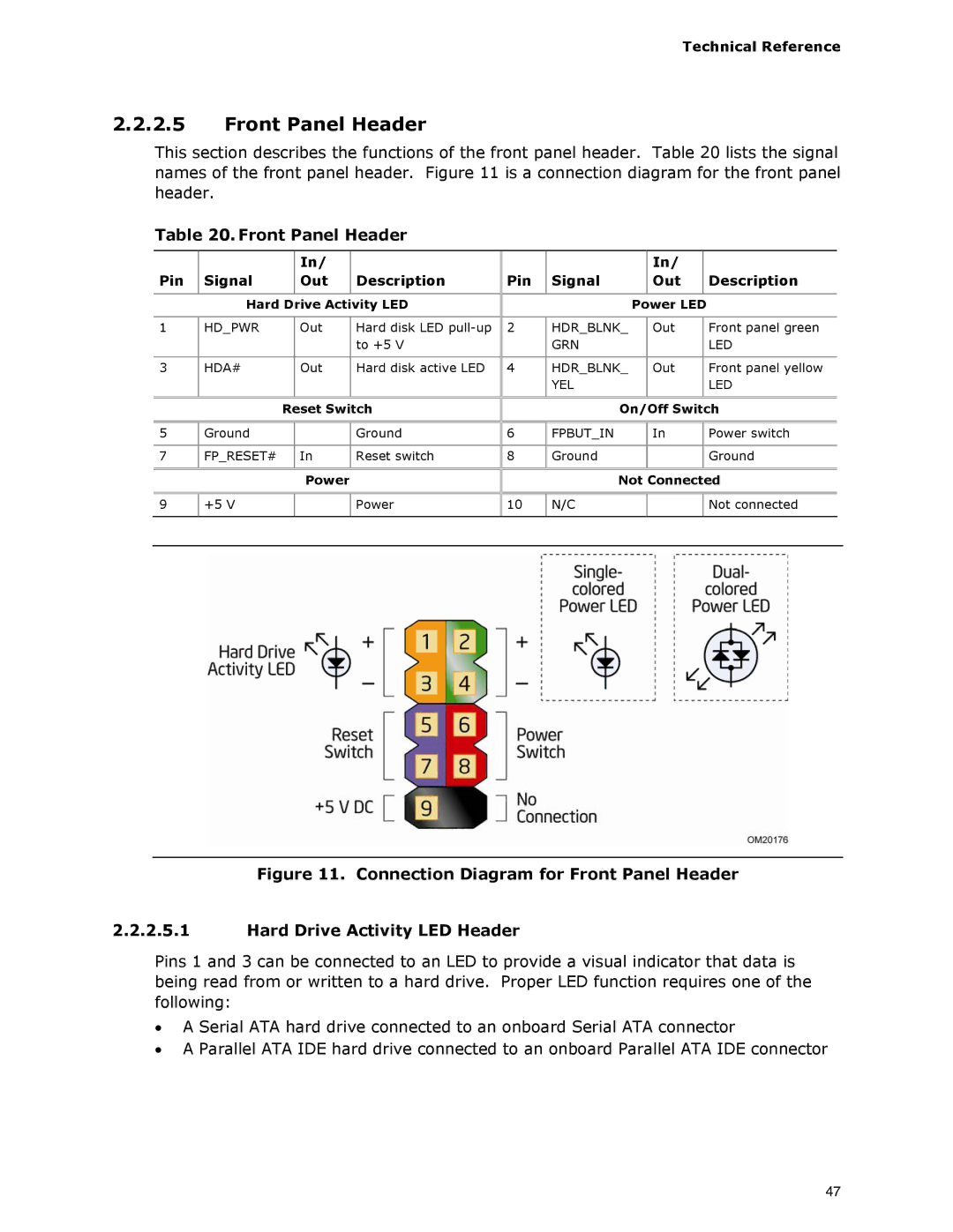
This section describes the functions of the front panel header. Table 20 lists the signal names of the front panel header. Figure 11 is a connection diagram for the front panel header.
Table 20. Front Panel Header
|
|
| In/ |
|
|
|
| In/ |
|
|
|
Pin | Signal |
| Out | Description | Pin | Signal |
| Out |
| Description |
|
|
|
|
|
|
|
|
|
|
|
| |
| Hard Drive Activity LED |
|
| Power LED |
|
| |||||
|
|
|
|
|
|
|
|
|
|
| |
1 | HD_PWR |
| Out | Hard disk LED | 2 | HDR_BLNK_ |
| Out |
| Front panel green |
|
|
|
|
| to +5 V |
| GRN |
|
|
| LED |
|
|
|
|
|
|
|
|
|
|
|
|
|
3 | HDA# |
| Out | Hard disk active LED | 4 | HDR_BLNK_ |
| Out |
| Front panel yellow |
|
|
|
|
|
|
| YEL |
|
|
| LED |
|
|
|
|
|
|
|
|
|
|
| ||
|
| Reset Switch |
| On/Off Switch |
| ||||||
|
|
|
|
|
|
|
|
|
|
| |
5 | Ground |
|
| Ground | 6 | FPBUT_IN |
| In |
| Power switch |
|
|
|
|
|
|
|
|
|
|
|
|
|
7 | FP_RESET# |
| In | Reset switch | 8 | Ground |
|
|
| Ground |
|
|
|
|
|
|
|
|
|
|
| ||
|
|
| Power |
|
| Not Connected |
| ||||
|
|
|
|
|
|
|
|
|
|
|
|
9 | +5 V |
|
| Power | 10 | N/C |
|
|
| Not connected |
|
|
|
|
|
|
|
|
|
|
|
|
|
|
|
|
|
|
|
|
|
|
|
|
|
Figure 11. Connection Diagram for Front Panel Header
2.2.2.5.1Hard Drive Activity LED Header
Pins 1 and 3 can be connected to an LED to provide a visual indicator that data is being read from or written to a hard drive. Proper LED function requires one of the following:
•A Serial ATA hard drive connected to an onboard Serial ATA connector
•A Parallel ATA IDE hard drive connected to an onboard Parallel ATA IDE connector
47