INSTALLATIONS
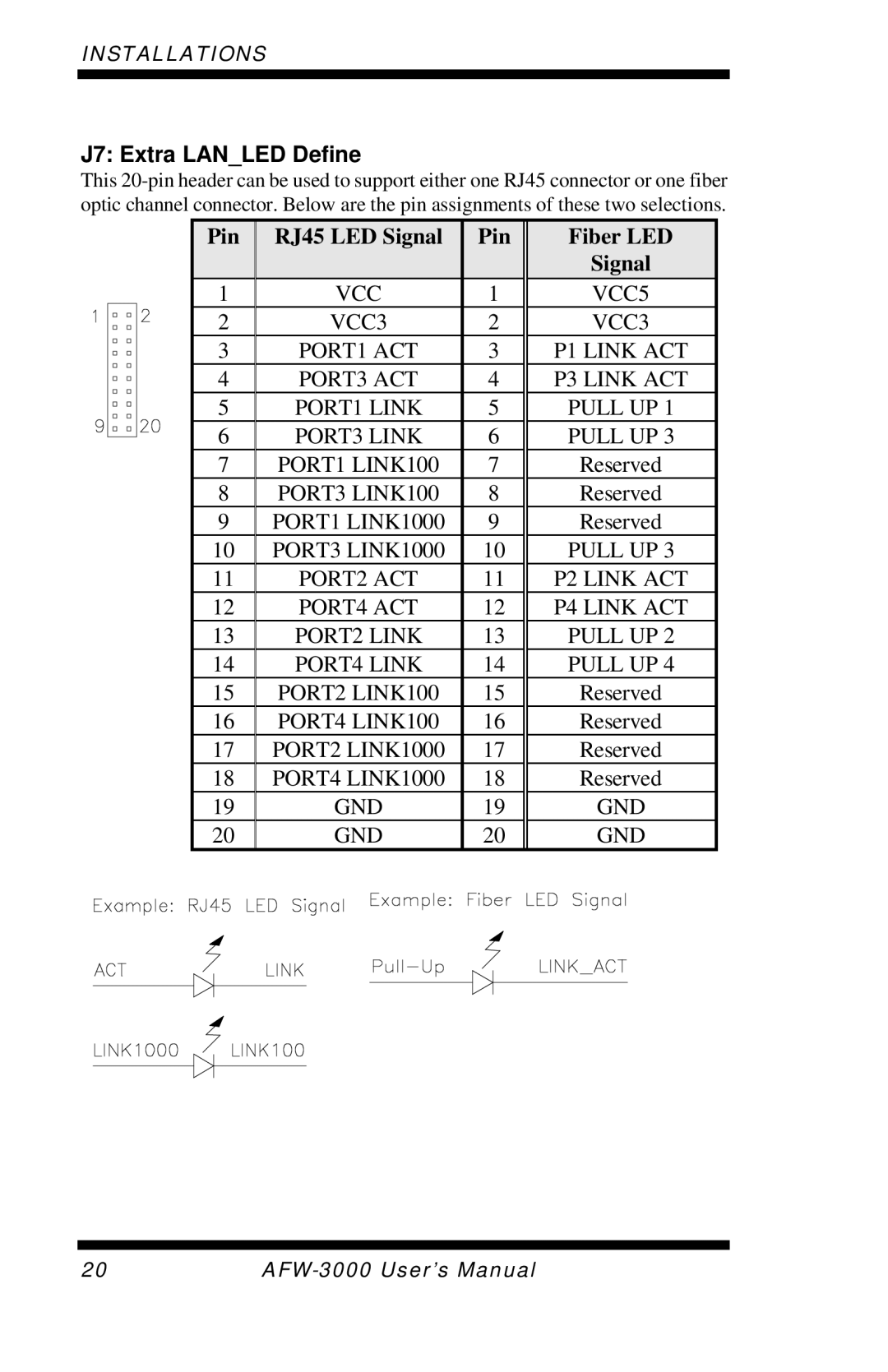
J7: Extra LAN_LED Define
This
Pin
1
2
3
4
5
6
7
8
9
10
11
12
13
14
15
16
17
18
19
20
|
|
| RJ45 LED Signal |
|
|
| Pin |
|
| ||||||||||||||||||||||||||||||||||||||
|
|
|
|
|
|
|
|
|
|
|
|
|
|
|
|
|
|
|
|
|
|
|
|
|
|
|
|
|
|
|
|
|
|
|
|
|
|
|
|
|
|
|
|
|
|
|
|
|
|
|
|
|
|
|
|
|
|
|
|
|
|
| VCC | 1 |
|
|
|
| |||||||||||||||||||||||||||
|
|
|
|
|
|
|
|
|
|
|
|
|
|
| VCC3 | 2 |
|
|
|
| |||||||||||||||||||||||||||
|
|
|
|
|
|
|
|
|
|
| PORT1 ACT | 3 |
|
|
|
| |||||||||||||||||||||||||||||||
|
|
|
|
|
|
|
|
|
|
| PORT3 ACT | 4 |
|
|
|
| |||||||||||||||||||||||||||||||
|
|
|
|
|
|
|
|
|
| PORT1 LINK | 5 |
|
|
|
| ||||||||||||||||||||||||||||||||
|
|
|
|
|
|
|
|
|
| PORT3 LINK | 6 |
|
|
|
| ||||||||||||||||||||||||||||||||
|
|
|
|
| PORT1 LINK100 | 7 |
|
|
|
| |||||||||||||||||||||||||||||||||||||
|
|
|
|
| PORT3 LINK100 | 8 |
|
|
|
| |||||||||||||||||||||||||||||||||||||
|
|
| PORT1 LINK1000 | 9 |
|
|
|
| |||||||||||||||||||||||||||||||||||||||
|
|
| PORT3 LINK1000 | 10 |
|
|
|
| |||||||||||||||||||||||||||||||||||||||
|
|
|
|
|
|
|
|
|
|
| PORT2 ACT | 11 |
|
|
|
| |||||||||||||||||||||||||||||||
|
|
|
|
|
|
|
|
|
|
| PORT4 ACT | 12 |
|
|
|
| |||||||||||||||||||||||||||||||
|
|
|
|
|
|
|
|
|
| PORT2 LINK | 13 |
|
|
|
| ||||||||||||||||||||||||||||||||
|
|
|
|
|
|
|
|
|
| PORT4 LINK | 14 |
|
|
|
| ||||||||||||||||||||||||||||||||
|
|
|
|
| PORT2 LINK100 | 15 |
|
|
|
| |||||||||||||||||||||||||||||||||||||
|
|
|
|
| PORT4 LINK100 | 16 |
|
|
|
| |||||||||||||||||||||||||||||||||||||
|
|
| PORT2 LINK1000 | 17 |
|
|
|
| |||||||||||||||||||||||||||||||||||||||
|
|
| PORT4 LINK1000 | 18 |
|
|
|
| |||||||||||||||||||||||||||||||||||||||
|
|
|
|
|
|
|
|
|
|
|
|
|
|
| GND | 19 |
|
|
|
| |||||||||||||||||||||||||||
|
|
|
|
|
|
|
|
|
|
|
|
|
|
| GND | 20 |
|
|
|
| |||||||||||||||||||||||||||
|
|
|
|
|
|
|
|
|
|
|
|
|
|
|
|
|
|
|
|
|
|
|
|
|
|
|
|
|
|
|
|
|
|
|
|
|
|
|
|
|
|
|
|
|
|
|
|
|
|
|
|
|
|
|
|
|
|
|
|
|
|
|
|
|
|
|
|
|
|
|
|
|
|
|
|
|
|
|
|
|
|
|
|
|
|
|
|
|
|
|
|
|
|
|
|
|
|
|
|
|
|
|
|
|
|
|
|
|
|
|
|
|
|
|
|
|
|
|
|
|
|
|
|
|
|
|
|
|
|
|
|
|
|
|
|
|
|
|
|
|
|
|
|
Fiber LED
Signal
VCC5
VCC3
P1 LINK ACT
P3 LINK ACT
PULL UP 1
PULL UP 3
Reserved
Reserved
Reserved
PULL UP 3
P2 LINK ACT
P4 LINK ACT
PULL UP 2
PULL UP 4
Reserved
Reserved
Reserved
Reserved
GND
GND
20 |
