ETX CD
Document Revision All not approved entries are marked
This page intentionally left blank
Table of Contents
Connector X4 IDE 1, IDE 2, Ethernet, Miscellaneous
Kontron Users Guide ETX CD
10.2.1
10.1
10.2
10.3
User Information
Technical Support
Asia Europe North/South America
Introduction
Introduction
ETX-CD
2x Serial ATA Sata 1x Parallel ATA IDE
ETX Documentation
ETX Benefits
Specifications
Functional Specifications
PCI 32 Intel ICH7
System Memory
Serial Digital Video Output Sdvo Intel 945GM
Enhanced Intelligent Drive Electronics Eide Intel ICH7
Trustes Platform Module TPM
Bios Phoenix, 1MB Flash-BIOS in Firmware Hub Flash Memory
AC ’97 Audio Intel 945GM
Block diagram
Mechanical Specifications
Electrical Specifications
ETX-CD Core Duo Processor T2500
Power Consumption Windows XP SP2
Cmos Battery Power Consumption
Mtbf
Environmental Specifications
Temperature
Humidity
Specifications
General Signal Description
ETX connectors
Connector Locations
ETX connectors
Connector X1 PCI bus, USB, Audio
Pin Signal
Pin Signal Description Type Termination Comment
Connector X1 Signal Levels
Pin 1-50 Power PCI USB Audio
Type Termination Comment
Pin 51-100 Power PCI USB Audio
Pin Signal Description
PCI Bus
Connector X1 Signal Description
3V Power Supply for External Components
Audio
Connector X2 ISA Bus
Connector X2 Signal Levels
Pin 1-50 Power ISA
Pin 51-100 Power ISA
Flat-Panel Interfaces
Connector X2 Signal Description
ISA Bus Slot
Lvds Interface Pinout Jili
Parallel Port Mode Pinout Floppy Support Mode Pinout
Parallel Port / Floppy Interfaces
DCD1# SLCT# WGATE# DSR1# Msclk CTS1# Msdat TXD1 Kbclk
Connector X3 Signal Levels
Pin 1-50 Power VGA Lcdtv
Pin 51-100 Power COM LPT Floppy KB/MS/IR
Serial Ports 1
Connector X3 Signal Description
VGA Output
PS/2 Keyboard
Floppy
IrDA
Parallel Port
Connector X4 Subsystems
Connector X4 IDE 1, IDE 2, Ethernet, Miscellaneous
Connector X4 Signal Levels
Pin 1-50Power IDE Ethernet Power control Misc
Pin Signal Description Type
Power Management
Connector X4 Signal Description
Power Control
IDE Ports
Sdvo Output
Feature Connector J11
Sdvo Connector and Flat Foil Cable
Miscellaneous Circuits
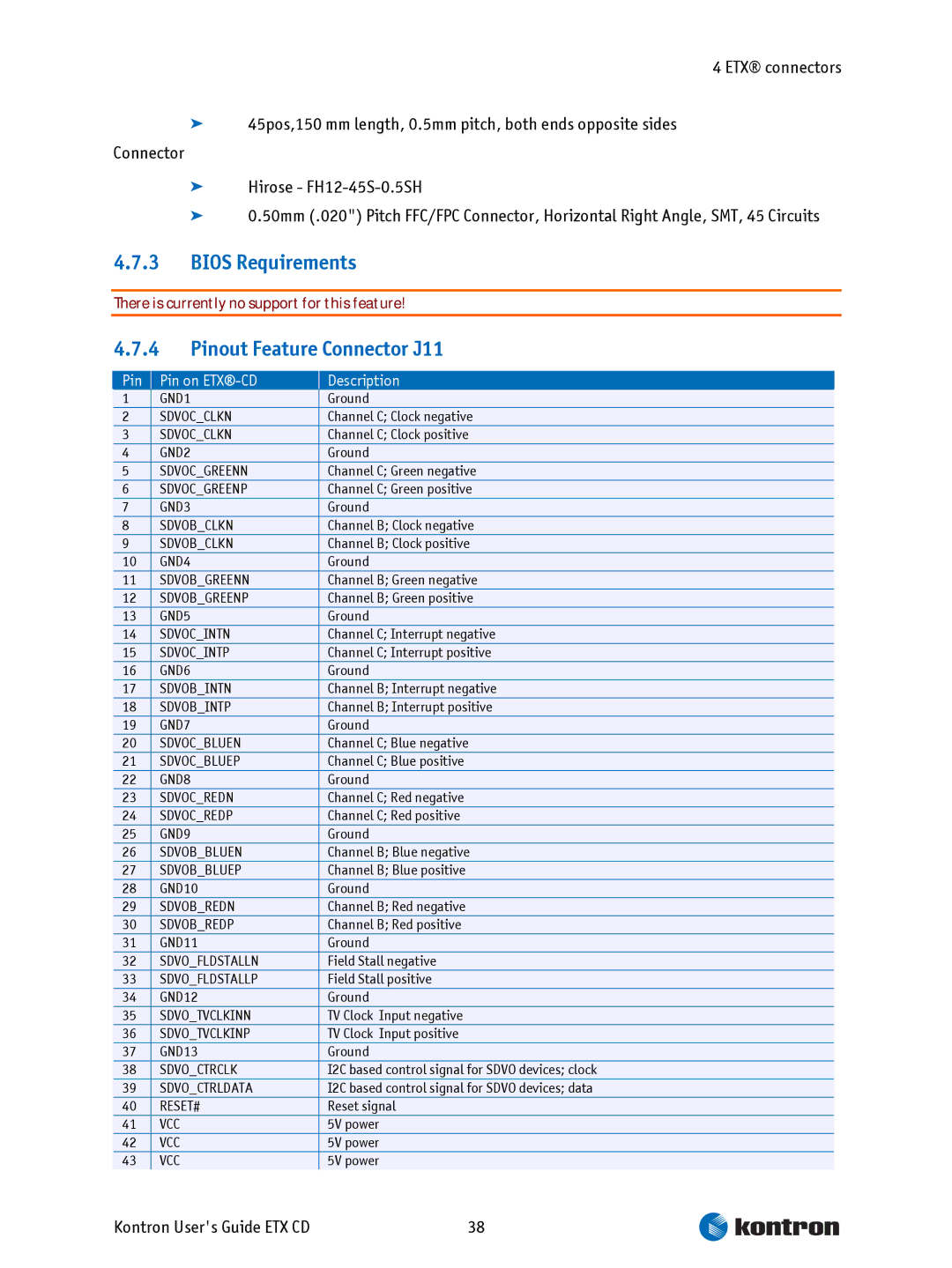
Pin Pin on ETX-CD Description
Bios Requirements
Pinout Feature Connector J11
Reserved
Special Features
Special Features
Watchdog Timer
Configuration
Thermal Management
Heatspreader Dimensions
Design Considerations
Design Considerations
Page
Thermal Monitor and Catastrophic Thermal Protection
I/O Apic vs 8259 PIC Interrupt mode
Important Technology Information
Active Cooling
Processor Performance Control
Summary
Passive Cooling
ETX-CD onboard Fan connector
Schematics of Fan control
Critical Trip Point
Location and Pinout of Fan connector J6
Pinout Kontron Users Guide ETX CD
Vcc = Imax continuous = 68 a Imax pulsed =
Bios Settings
Electrical characteristics
Acpi Suspend Modes and Resume Events
Processor Clock Throttling
Page
Interrupt Request IRQ Lines
8259 PIC mode
System Resources
Used For Available Available for PCI Comment
Direct Memory Access DMA Channels
Apic mode
Peripheral Component Interconnect PCI Devices
Memory Area
I/O Address Map
Inter-IC I2C Bus
JILI-I2C Bus
Windows
Limitations
ISA Bus
Limitations
Setup Guide
Bios Operation
Determining the Bios Version
Start Phoenix Bios Setup Utility
Item Specific Help Window
Selecting an Item
Displaying Submenus
General Help Window
Bios Setup Menus
Info Screen
Disabled
Main Menu
IDE Channels Submenu
Auto
Advanced
Advanced Chipset Control
Feature bit to always return
CPU Control
Default
Chipset control
Integrated Video
Dvmt
ISA Options
PCI/PNP Configuration
Other
PCI/PNP ISA UMB Region Exclusion
PCI/PNP ISA IRQ Resource Exclusion
Cache Memory
Write Protect
Device Configuration
Lan Options
Super I/O Controller Options
IRQ4
USB ports
Console Redirection
Keyboard Features Submenu
30/sec
Hardware Monitor
Watchdog Settings
Display Control
CRT + LFP
Miscellaneous Submenu
Security Menu
Power Menu
Yes
CPU Thermal Control Circuit
POR
Boot Menu
Feature Option Descpription
Feature Description
Exit Menu
Updating or Restoring Bios
Cannot flash when memory managers are present
Preventing Problems When Updating or Restoring Bios
Appendix a Jida Standard
Appendix a Jida Standard
Jida Information
Buses
12.1.1 ISA, Standard PS/2 Connectors
Appendix B PC Architecture Information
12.1.2 PCI/104
Serial ATA
Ports
12.2.1 RS-232 Serial
12.2.3 USB
Kontron Users Guide ETX CD
Rev. Date Author Changes
Appendix C Document Revision
Appendix C Document Revision