GA-N650SLI-DS4 specifications
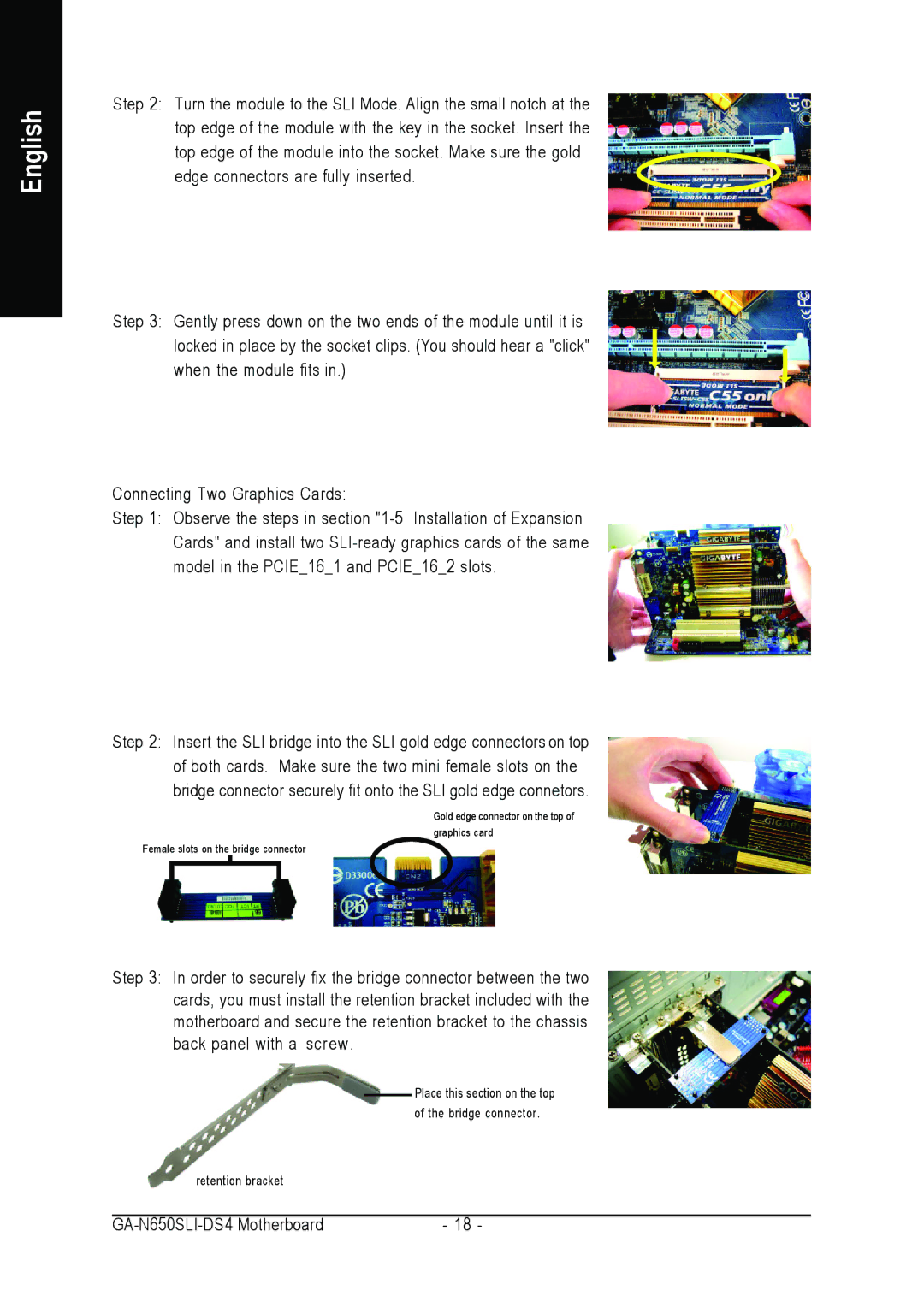
The Intel GA-N650SLI-DS4 is a notable motherboard designed for gaming and high-performance computing enthusiasts. This ATX motherboard supports Intel processors and is built on the NVIDIA nForce 650i chipset, making it a solid choice for users looking to harness the power of dual graphics cards through SLI technology.One of the standout features of the GA-N650SLI-DS4 is its support for NVIDIA's SLI technology, which allows users to connect two compatible NVIDIA graphics cards for enhanced gaming performance. This feature is particularly appealing to gamers who demand high frame rates and advanced graphical settings. With dual PCI Express x16 slots, users can easily install multiple GPUs and benefit from improved rendering and smoother gameplay.
Another significant aspect of this motherboard is its DDR2 memory support. The GA-N650SLI-DS4 can accommodate up to 8GB of DDR2 RAM, which provides ample memory for modern applications and multitasking. The board supports memory speeds ranging from 533 MHz to 800 MHz, ensuring that users can take advantage of the latest memory technology available at the time.
The layout of the GA-N650SLI-DS4 is thoughtfully designed, featuring an impressive array of connectivity options. It includes multiple SATA ports for connecting storage devices, supporting RAID configurations for data redundancy and performance. Additionally, the motherboard comes equipped with a variety of USB ports, including USB 2.0 and headers for front panel connections, allowing users to connect peripherals with ease.
In terms of audio, the board features integrated 8-channel HD audio, creating a rich sound experience for gaming and multimedia. The Realtek ALC888 audio codec ensures high fidelity sound, providing an immersive experience for gamers and media consumers alike.
The GA-N650SLI-DS4 also utilizes advanced cooling technologies to keep the system operating efficiently. With dedicated heatsinks for the chipset and power phases, users can enjoy improved thermal management, essential for maintaining performance during extended gaming sessions.
In summary, the Intel GA-N650SLI-DS4 is a well-rounded motherboard that caters to gamers and power users alike. Its support for dual GPUs, ample memory capacity, a variety of connectivity options, and robust audio capabilities make it a strong contender for anyone looking to build a high-performance system. As technology continues to evolve, the features of the GA-N650SLI-DS4 remain relevant, providing a solid foundation for an impressive gaming setup.

