Manuals
/
Intel
/
Computer Equipment
/
Computer Hardware
Intel
MB898 J8: System Function Connector, Speaker Pins, Pin #, Signal Name, Power LED Pins
Models:
MB898F
MB898
MB898RF
1
25
62
62
Download
62 pages
59.34 Kb
22
23
24
25
26
27
28
29
Specs
Install
Signal Name
Password
Watchdog Timer Configuration
Dimension
PNP/PCI Configurations
IDE DMA Transfer Access
Press <DEL> to Enter Setup
Connectors on MB898
Page 25
Image 25
Page 24
Page 26
Page 25
Image 25
Page 24
Page 26
Contents
Industrial Motherboard
Socket LGA775 Pentium Intel Q965 Chipset
Version
MB898/MB898F MB898RF
Acknowledgments
BIOS Setup
Installations
Drivers Installation
Introduction
This page is intentionally left blank
Introduction
Checklist
INTRODUCTION
Product Description
MB898/MB898F
Specifications
MB898RF supports 6 x SATA with RAID
System
Board Dimensions
Installations
ATX Power Installation
Installing the CPU
Dual Channel Memory Configuration
Installing the Memory
Setting the Jumpers
Jumper Locations on MB898/MB898F
JP1: Select the Boot Device Factory used only
JBAT1: Clear CMOS Contents
JP5: Configure and Recovery Factory use only
Setting
JP11: Processor Setting
JP6: IDE DMA Mode Setting
Connectors on MB898
Connector Locations on MB898/MB898F
ATX2: ATX 12V Power Connector
ATX1: 24-pinATX Power Connector
Signal Name
Pin #
CN1: Parallel Port Connector
VGA1: VGA CRT Connector
CN2, J10, J6, J5: COM1/2/3/4 Serial Ports
CN3: PS/2 Keyboard and PS/2 Mouse Connectors
USB_LAN1: 10/100 or GbE RJ-45and USB4/5 Connector
CN4: Audio Connector USB6: USB6/7 Connector
F USB1 USB0/USB1 Connector
Note: 10/100 LAN for MB898; Gigabit LAN for
F USB3 USB8/USB9 Connector
F_USB2: USB2/USB3 Connector
Note: S_ATA5 and S_ATA6 MB898F only
CPU_FAN1: CPU Fan Power Connector
IDE1: Primary IDE Connectors
PWR_FAN1: POWER Fan Power Connector
Pin # Signal Name
NB_FAN1: Northbridge Fan Power Connectors
SYS_FAN1: SYSTEM Fan Power Connector
J2: HDMI Audio Connector
J1: Audio Front Header
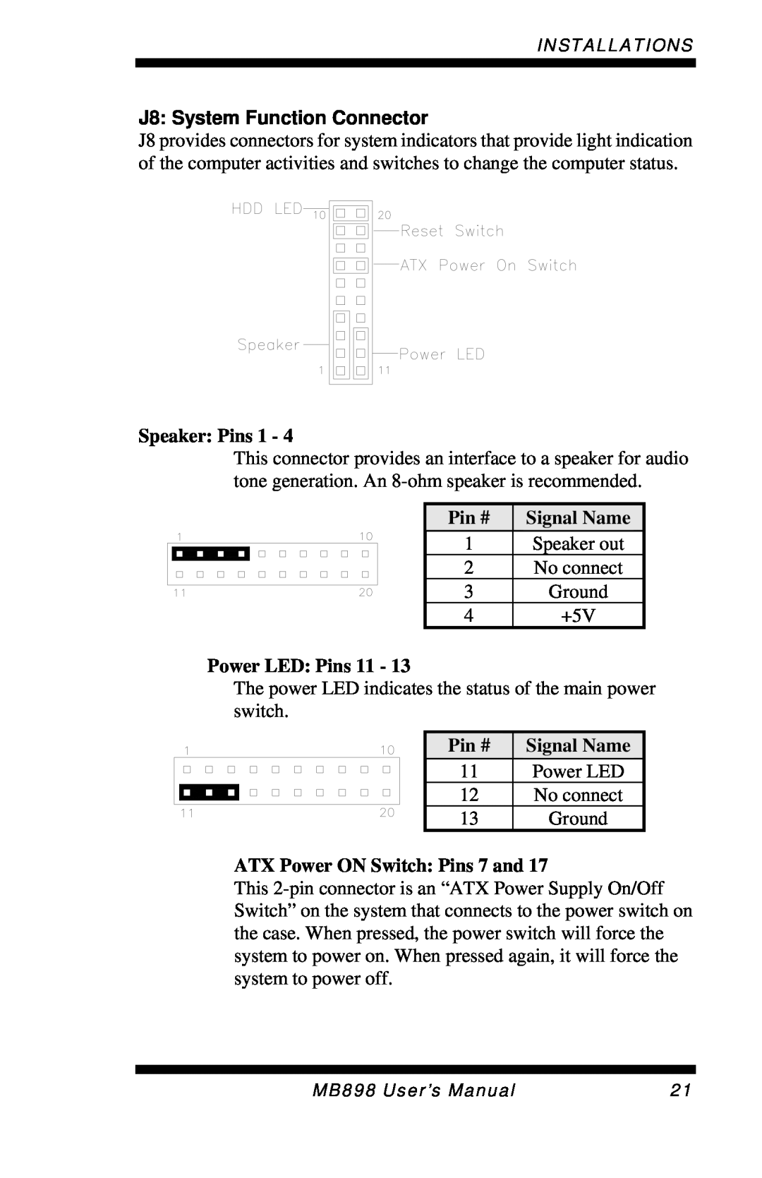
Speaker Pins
J8: System Function Connector
Power LED Pins
ATX Power ON Switch: Pins 7 and
J11: IrDA Connector
PCIE_1: x16 PCI Express Slot
J12: Digital I/O Connector 4 in, 4 out
PCIE_2, PCIE_3: x1 PCI Express Slots
PCI1, PCI2, PCI3, PCI4: PCI Slots J9: CF Socket
Watchdog Timer Configuration
MB898 User’s Manual
INSTALLATIONS
MB898 User’s Manual
INSTALLATIONS
MB898 User’s Manual
INSTALLATIONS
MB898 User’s Manual
BIOS Setup
BIOS Setup
BIOS Introduction
Press <DEL> to Enter Setup
MB898 User’s Manual
Date
Standard CMOS Setup
IDE Channel Master/Slave
Time
Landing Zone : Landing zone
Video
Drive A / Drive B
Halt On
CPU Feature
Advanced BIOS Features
Hard Disk Boot Priority
Virus Warning
First/Second/Third Boot Device
Quick Power On Self Test
Boot Other Device
Boot Up Floppy Seek
Typematic Delay Msec
Typematic Rate Chars/Sec
Security Option
APIC Mode
System BIOS Cacheable
Advanced Chipset Features
On-ChipVGA Setting
Memory Hole At 15M-16M
OnChip IDE Device
Integrated Peripherals
SuperIO Device
Onboard Device
IDE HDD Block Mode
IDE DMA Transfer Access
OnChip Secondary PCI IDE
IDE Primary/Secondary Master/Slave PIO
KB Power ON Password
Power ON Function
Hot Key Power ON
SATA Mode
Intel 82562V LAN Control MB898
Parallel Port Mode
USB 1.0 Controller
USB 2.0 Controller
Power Management
Power Management Setup
ACPI Function
ACPI Suspend
Resume by Alarm
HDD Power Down
Reload Global Timer Events
Video Off Method
Reset Configuration Data
PNP/PCI Configurations
Init Display First
Resources Controlled by
CPU Warning Temperature
PC Health Status
Shutdown Temperature
Temperatures/Fan Speeds/Voltages
Auto Detect PCI Clk
Frequency/Voltage Control
Spread Spectrum
Load Optimized Defaults
Load Fail-SafeDefaults
Set Supervisor/User Password
Save & Exit Setup
Chipset Software Installation Utility錯誤! 尚未定義書籤。
Drivers Installation
Intel LAN Drivers Installation
Intel Q965
Intel Q965 Chipset Software Installation Utility
MB898 User’s Manual
Intel Q965 Chipset Graphics Driver
MB898 User’s Manual
Realtek Codec Audio Driver Installation
Intel LAN Drivers Installation
MB898 User’s Manual
A. I/O Port Address Map
Appendix
Level
B. Interrupt Request Lines IRQ
Top
Page
Image
Contents