|
|
|
|
|
|
|
|
|
| Configuration |
|
|
|
|
|
|
|
|
|
|
|
| |
| Function Prompt |
| Selection or Range of Setting |
|
|
| Parameter | ||||
| Lower Display |
| Upper Display |
|
|
| Definition | ||||
| English | Numeric |
| English | Numeric |
|
|
|
|
|
|
|
| Code |
|
| Code |
|
|
|
|
|
|
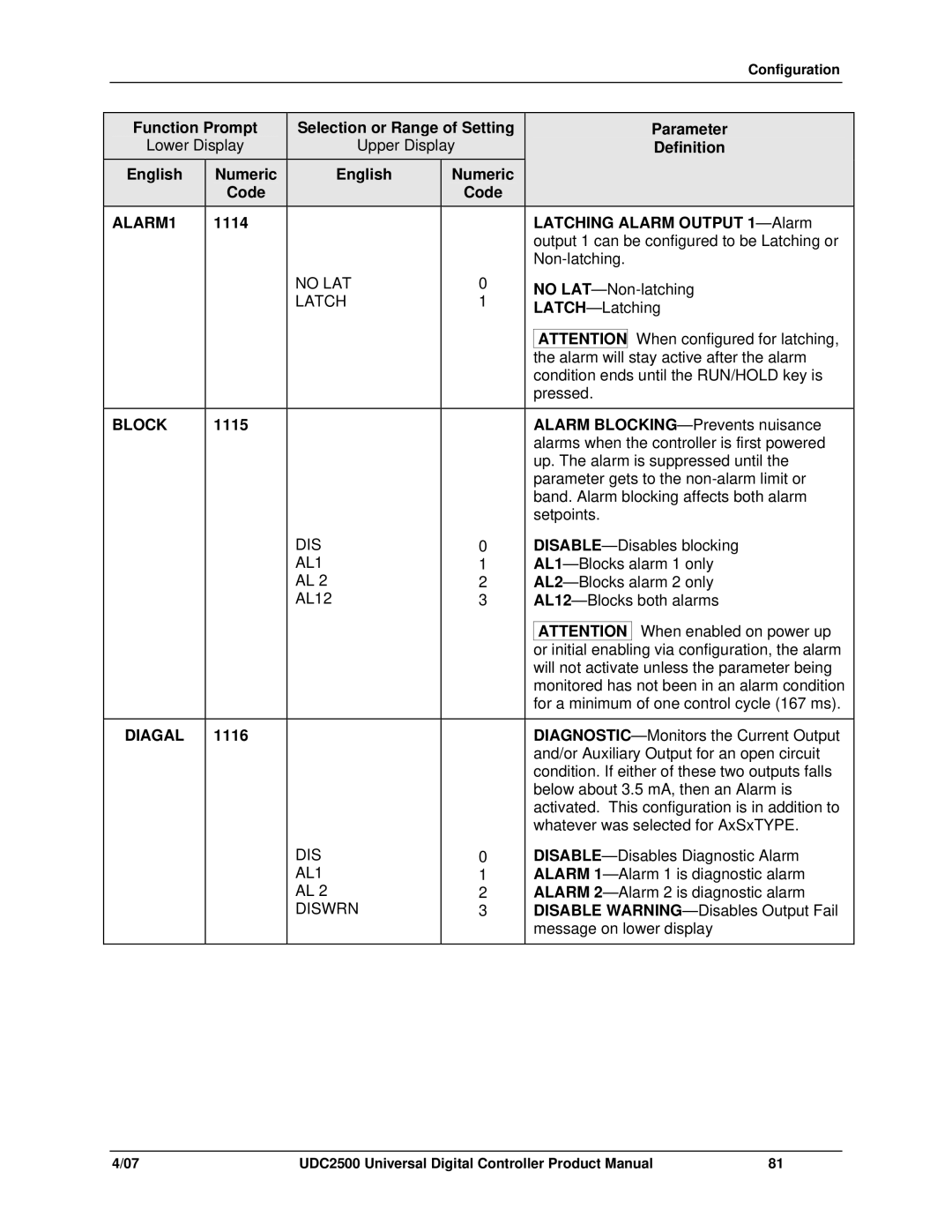
| ALARM1 | 1114 |
|
|
|
|
| LATCHING ALARM OUTPUT | |||
|
|
|
|
|
|
|
| output 1 can be configured to be Latching or | |||
|
|
|
|
|
|
|
| ||||
|
|
|
| NO LAT | 0 |
|
| NO | |||
|
|
|
| LATCH | 1 |
|
| ||||
|
|
|
|
|
| ||||||
|
|
|
|
|
|
|
| ||||
|
|
|
|
|
|
|
|
|
| When configured for latching, | |
|
|
|
|
|
|
|
| ATTENTION | |||
|
|
|
|
|
|
|
| the alarm will | stay active after the alarm | ||
|
|
|
|
|
|
|
| condition ends until the RUN/HOLD key is | |||
|
|
|
|
|
|
|
| pressed. | |||
|
|
|
|
|
|
|
|
| |||
| BLOCK | 1115 |
|
|
|
|
| ALARM | |||
|
|
|
|
|
|
|
| alarms when the controller is first powered | |||
|
|
|
|
|
|
|
| up. The alarm is suppressed until the | |||
|
|
|
|
|
|
|
| parameter gets to the | |||
|
|
|
|
|
|
|
| band. Alarm blocking affects both alarm | |||
|
|
|
|
|
|
|
| setpoints. | |||
|
|
|
| DIS | 0 |
|
| ||||
|
|
|
| AL1 | 1 |
|
| ||||
|
|
|
| AL 2 | 2 |
|
| ||||
|
|
|
| AL12 | 3 |
|
| ||||
|
|
|
|
|
|
|
|
| When enabled on power up | ||
|
|
|
|
|
|
|
| ATTENTION | |||
|
|
|
|
|
|
|
| or initial enabling via configuration, the alarm | |||
|
|
|
|
|
|
|
| will not activate unless the parameter being | |||
|
|
|
|
|
|
|
| monitored has not been in an alarm condition | |||
|
|
|
|
|
|
|
| for a minimum of one control cycle (167 ms). | |||
|
|
|
|
|
|
|
|
| |||
| DIAGAL | 1116 |
|
|
|
|
| ||||
|
|
|
|
|
|
|
| and/or Auxiliary Output for an open circuit | |||
|
|
|
|
|
|
|
| condition. If either of these two outputs falls | |||
|
|
|
|
|
|
|
| below about 3.5 mA, then an Alarm is | |||
|
|
|
|
|
|
|
| activated. This configuration is in addition to | |||
|
|
|
|
|
|
|
| whatever was selected for AxSxTYPE. | |||
|
|
|
| DIS | 0 |
|
| ||||
|
|
|
| AL1 | 1 |
|
| ALARM | |||
|
|
|
| AL 2 | 2 |
|
| ALARM | |||
|
|
|
| DISWRN | 3 |
|
| DISABLE | |||
|
|
|
|
|
|
|
| message on lower display | |||
|
|
|
|
|
|
|
|
|
|
|
|
4/07 | UDC2500 Universal Digital Controller Product Manual | 81 |