Configuration
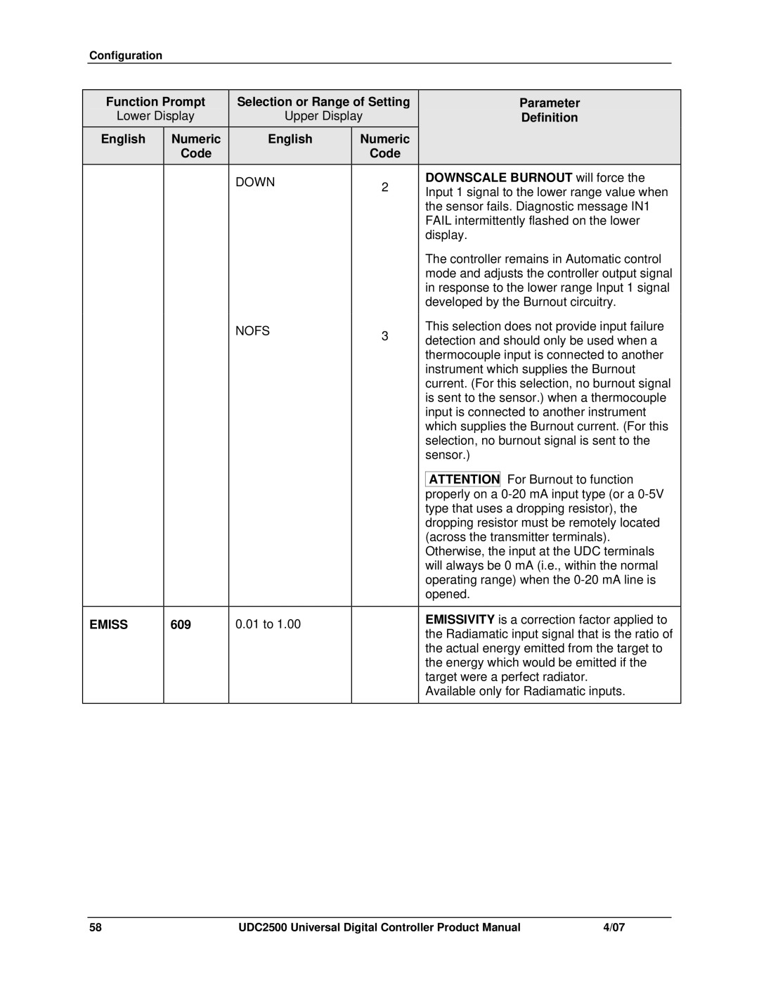
| Function Prompt |
| Selection or Range of Setting |
|
| Parameter | ||||
| Lower Display |
| Upper Display |
|
| Definition | ||||
| English | Numeric |
|
| English | Numeric |
|
|
|
|
|
| Code |
|
|
| Code |
|
|
|
|
|
|
|
|
| DOWN | 2 |
|
| DOWNSCALE BURNOUT will force the | |
|
|
|
|
|
|
|
| Input 1 signal to the lower range value when | ||
|
|
|
|
|
|
|
|
| the sensor fails. Diagnostic message IN1 | |
|
|
|
|
|
|
|
|
| FAIL intermittently flashed on the lower | |
|
|
|
|
|
|
|
|
| display. | |
|
|
|
|
|
|
|
|
| The controller remains in Automatic control | |
|
|
|
|
|
|
|
|
| mode and adjusts the controller output signal | |
|
|
|
|
|
|
|
|
| in response to the lower range Input 1 signal | |
|
|
|
|
|
|
|
|
| developed by the Burnout circuitry. | |
|
|
|
|
| NOFS | 3 |
|
| This selection does not provide input failure | |
|
|
|
|
|
|
| detection and should only be used when a | |||
|
|
|
|
|
|
|
| |||
|
|
|
|
|
|
|
|
| thermocouple input is connected to another | |
|
|
|
|
|
|
|
|
| instrument which supplies the Burnout | |
|
|
|
|
|
|
|
|
| current. (For this selection, no burnout signal | |
|
|
|
|
|
|
|
|
| is sent to the sensor.) when a thermocouple | |
|
|
|
|
|
|
|
|
| input is connected to another instrument | |
|
|
|
|
|
|
|
|
| which supplies the Burnout current. (For this | |
|
|
|
|
|
|
|
|
| selection, no burnout signal is sent to the | |
|
|
|
|
|
|
|
|
| sensor.) | |
|
|
|
|
|
|
|
|
|
| For Burnout to function |
|
|
|
|
|
|
|
|
| ATTENTION | |
|
|
|
|
|
|
|
|
| properly on a | |
|
|
|
|
|
|
|
|
| type that uses a dropping resistor), the | |
|
|
|
|
|
|
|
|
| dropping resistor must be remotely located | |
|
|
|
|
|
|
|
|
| (across the transmitter terminals). | |
|
|
|
|
|
|
|
|
| Otherwise, the input at the UDC terminals | |
|
|
|
|
|
|
|
|
| will always be 0 mA (i.e., within the normal | |
|
|
|
|
|
|
|
|
| operating range) when the | |
|
|
|
|
|
|
|
|
| opened. | |
|
|
|
|
|
|
|
|
|
| |
| EMISS | 609 |
|
| 0.01 to 1.00 |
|
|
| EMISSIVITY is a correction factor applied to | |
|
|
|
|
|
| the Radiamatic input signal that is the ratio of | ||||
|
|
|
|
|
|
|
|
| ||
|
|
|
|
|
|
|
|
| the actual energy emitted from the target to | |
|
|
|
|
|
|
|
|
| the energy which would be emitted if the | |
|
|
|
|
|
|
|
|
| target were a perfect radiator. | |
|
|
|
|
|
|
|
|
| Available only for Radiamatic inputs. | |
|
|
|
|
|
|
|
|
|
|
|
58 | UDC2500 Universal Digital Controller Product Manual | 4/07 |