Input Calibration
Procedure
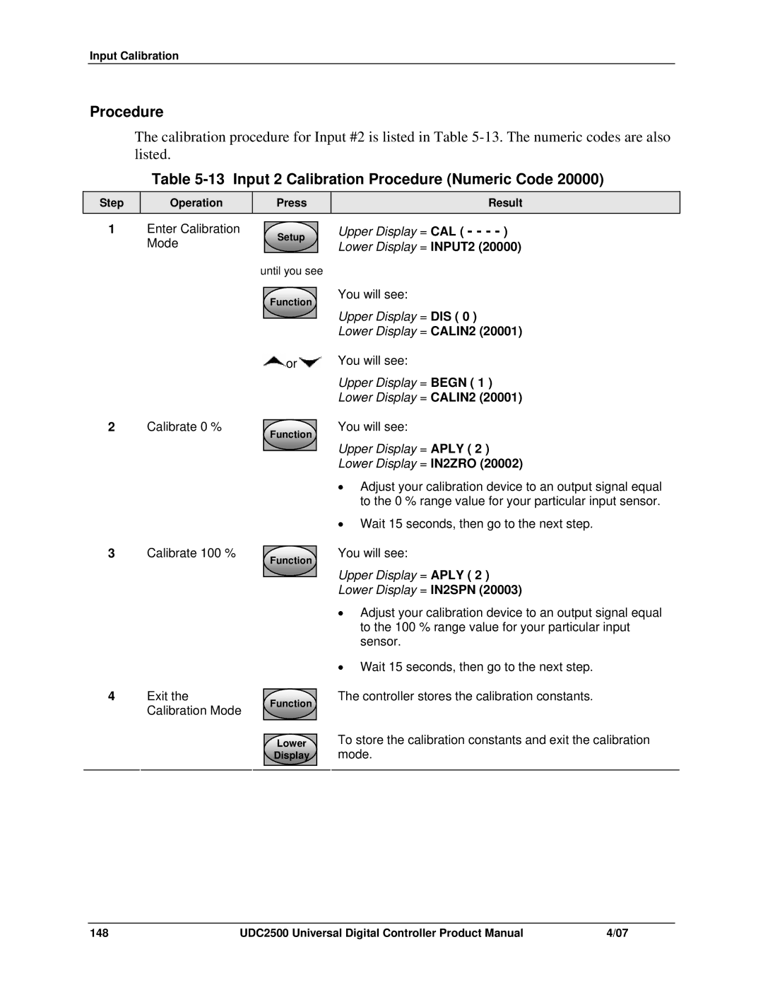
The calibration procedure for Input #2 is listed in Table
Table 5-13 Input 2 Calibration Procedure (Numeric Code 20000)
Step
Operation
Press
Result
1 | Enter Calibration | Setup | Upper Display = CAL ( - - - - ) |
| Mode |
| Lower Display = INPUT2 (20000) |
until you see
Function
You will see:
Upper Display = DIS ( 0 )
Lower Display = CALIN2 (20001)
![]() or
or![]() You will see:
You will see:
Upper Display = BEGN ( 1 )
Lower Display = CALIN2 (20001)
2Calibrate 0 %
Function
You will see:
Upper Display = APLY ( 2 )
Lower Display = IN2ZRO (20002)
•Adjust your calibration device to an output signal equal to the 0 % range value for your particular input sensor.
•Wait 15 seconds, then go to the next step.
3Calibrate 100 %
Function
You will see:
Upper Display = APLY ( 2 )
Lower Display = IN2SPN (20003)
•Adjust your calibration device to an output signal equal to the 100 % range value for your particular input sensor.
•Wait 15 seconds, then go to the next step.
4Exit the Calibration Mode
Function
Lower
Display
The controller stores the calibration constants.
To store the calibration constants and exit the calibration mode.
148 | UDC2500 Universal Digital Controller Product Manual | 4/07 |